| Library of Shiunten | |||||
| Entrance | Information | Computer Section |
Building and Repairs Section |
Transportation Bureau |
Link |
|
This web site is only compatible with Japanese text. The Japanese version of this article can be found on a separate page. Connecting an FDD for PC/AT compatible computer to PC-9821
|
||||||||||||||||||||||||||||||||||||||||||||||||||||||||||||||||||||||||||||||||||||||||||||||||||||||||||||||||||||||||||||||||||||||||||||||||||||||||||||||||||||||||||||||||||||||||||||||||||||||||||||||||||||||||||||||||||||||||||||||||||||||||||||||||||||||||||||||||||||||||||||||||||||||||||||||||||||||||||||||||||||||||||||||||||||||||||||||||||||||||||||||||||||||||||||||
| table of contents |
|---|
As a result of testing multiple FDDs, we were able to operate it on the PC-9821 Ls12 by modifying it as shown in the drawing shown in the table below.
In the table below, plot diagrams and reference photographs that outline the remodeling points are organized by FDD. After checking the outline of the modification contents in the drawing, please observe the difference before and after the modification with the reference photo. Even if the drawings are drawn too finely, it will only be difficult to deal with differences in production lots, so I dare to list only the important items.
The materials shown in the table below are all based on the assumption that the PC-9800 series is used, but they can be applied to other models.
For example, in the case of the MSX series model with a 34-pin interface, the modification to enable output of the READY signal is performed as shown in the figure. Replacing the Density (Mode Select) signal can be omitted. Instead, it seems that it is necessary to fix the FDD operation mode to 2DD mode and additionally modify the Drive Select and Motor ON signals.
For more information, please see the article "FS-FD1A drive conversion" by Niga HP on PS2Linux DASH. (The author of this article does not own an MSX and has not been able to verify this.)
The precautions common to all the drawings shown in the table below are shown below.
| List of common precautions |
|---|
|
The following is a list of FDD modification drawings and reference photos, as well as the results of operation tests after modification. When referring to the drawings and reference photos, be sure to also refer to the special notes at the end of the list.
| List of FDD modification results | ||||||||||
|---|---|---|---|---|---|---|---|---|---|---|
| FDD Model No. *1 |
Drawings | Reference photo |
Available format types for PC-9821 |
Note | ||||||
| Before renovation |
After renovation |
2HD (1.44) *2 |
2HD (1.23) *3 |
2DD | ||||||
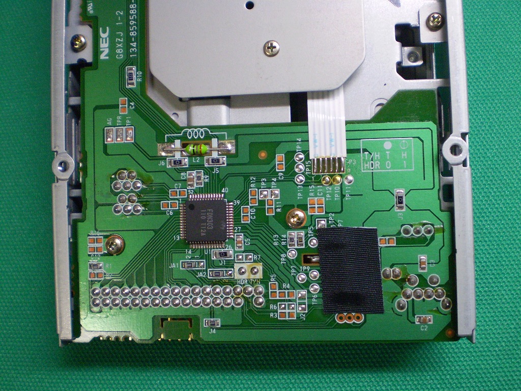
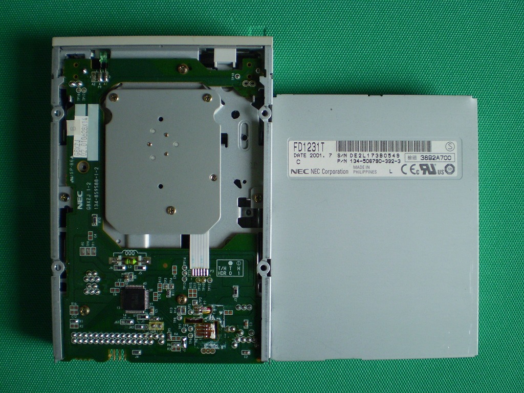
| FD1231T (FDN303) [6pin] |
DXF | whole | Partial details |
whole | Partial details |
OK | OK | OK | *4 *5 *6 |
|
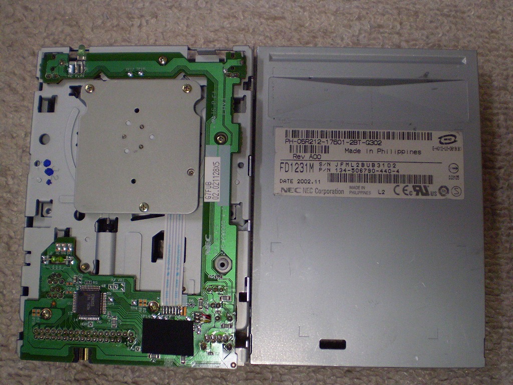
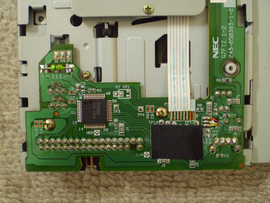
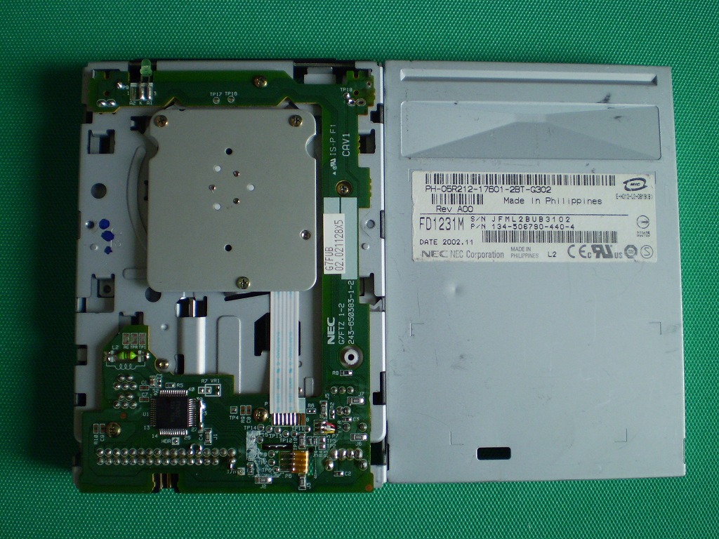
| FD1231M (FDN303) [6pin] |
DXF | whole | Partial details |
whole | Partial details |
OK | OK | OK | ||
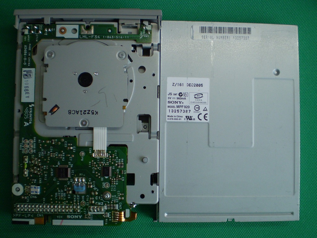
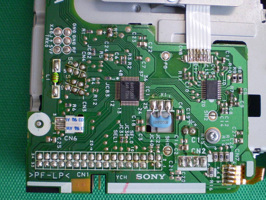
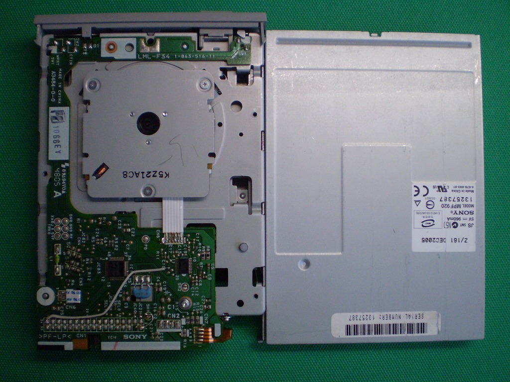
| MPF920 (BH9558KV) [35pin] |
DXF | whole | Partial details |
whole | Partial details |
OK | OK | *7 *8 |
||
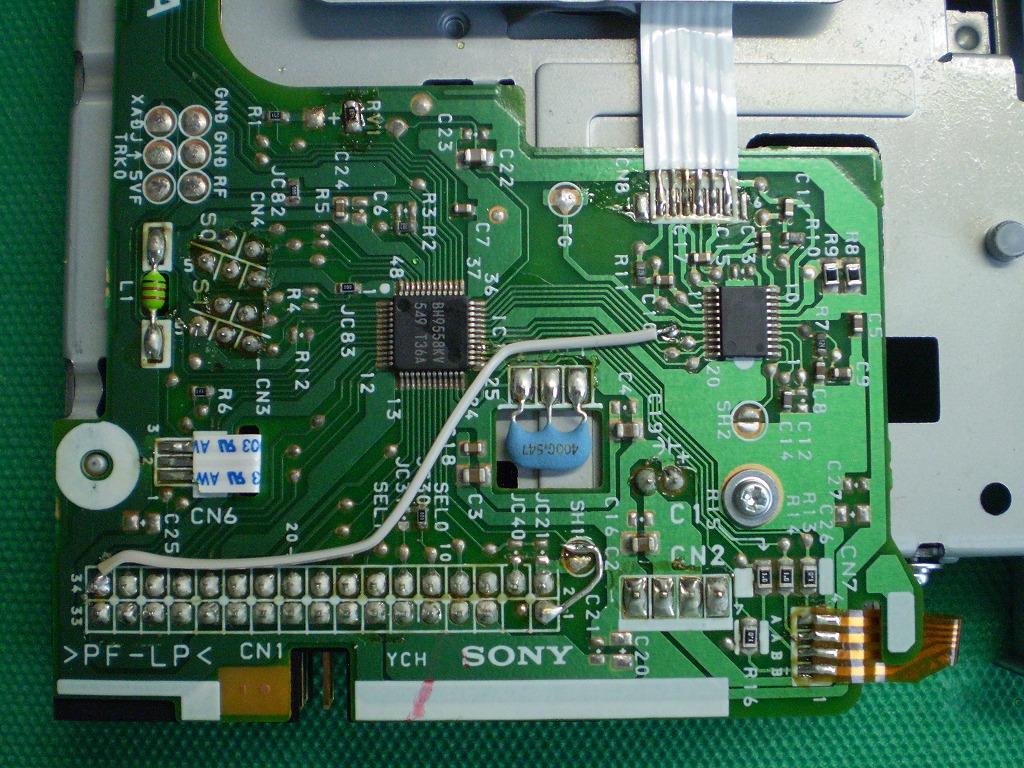
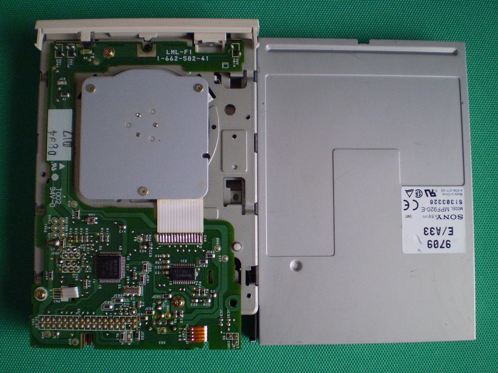
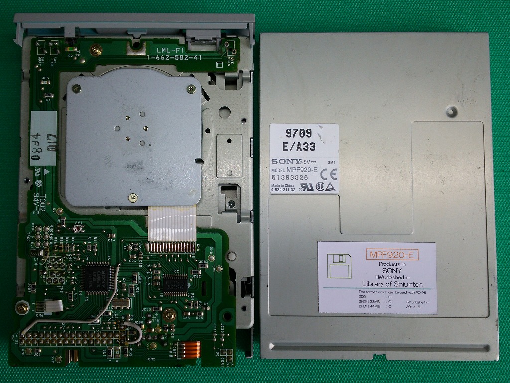
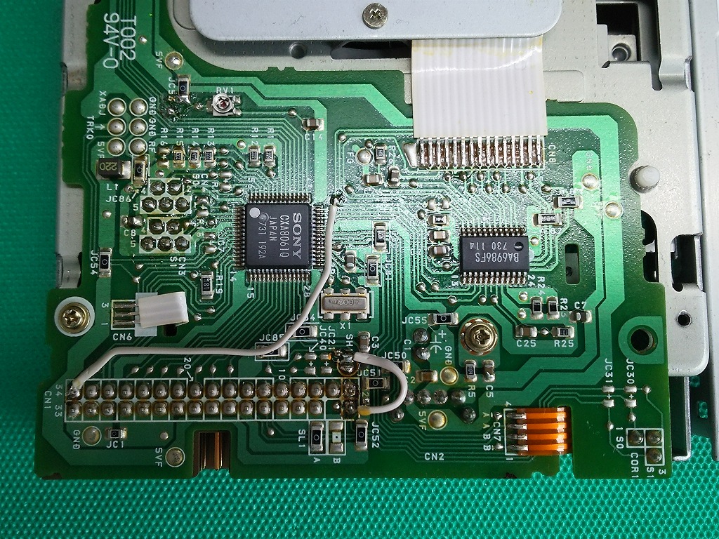
| MPF920-E (CXA8061Q) [42pin] |
DXF | whole | Partial details |
whole | Partial details |
OK | OK | *15 | *7 *9 |
|
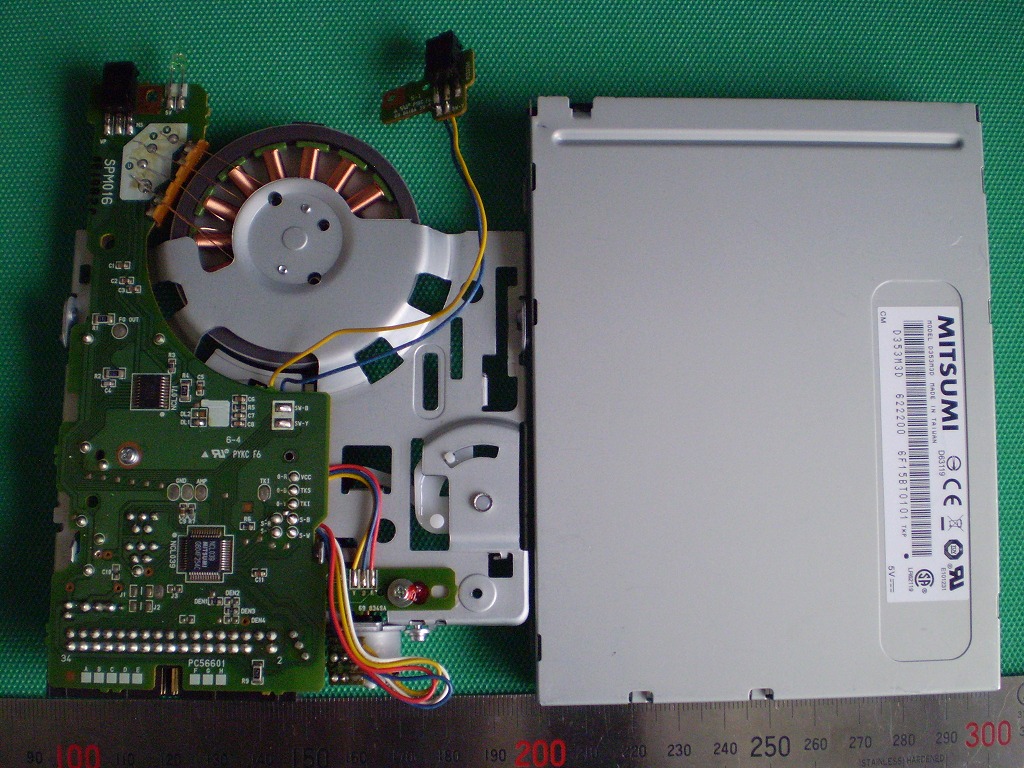
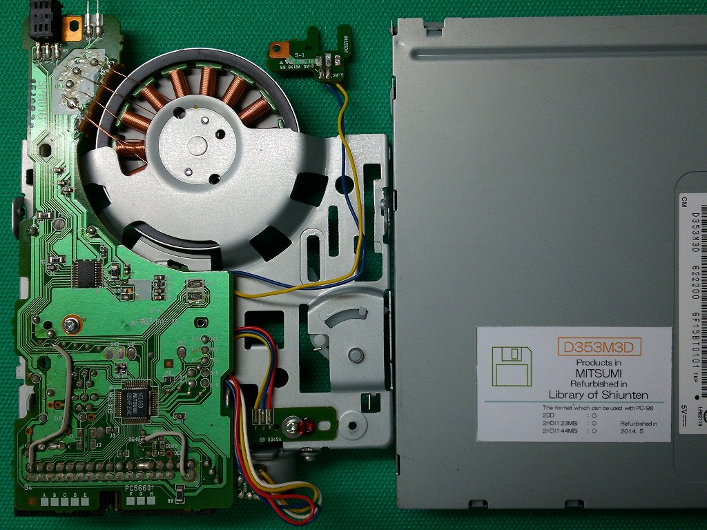
| D353M3D (NCL039) [35pin] |
DXF | whole | Partial details |
whole | Partial details |
OK | OK | *16 | *7 *10 |
|
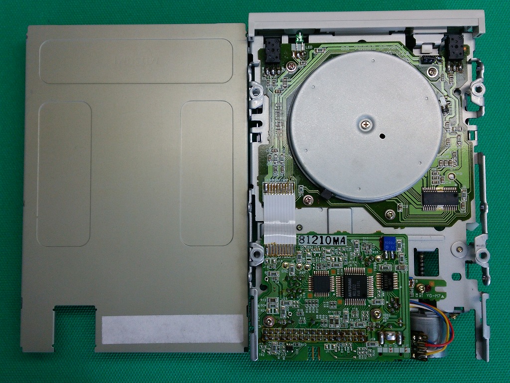
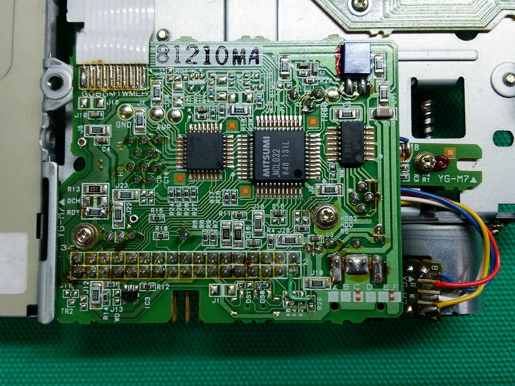
| D353-T5 (NCL032) [32pin] |
DXF | whole | Partial details |
whole | Partial details |
OK | OK | *7 | ||
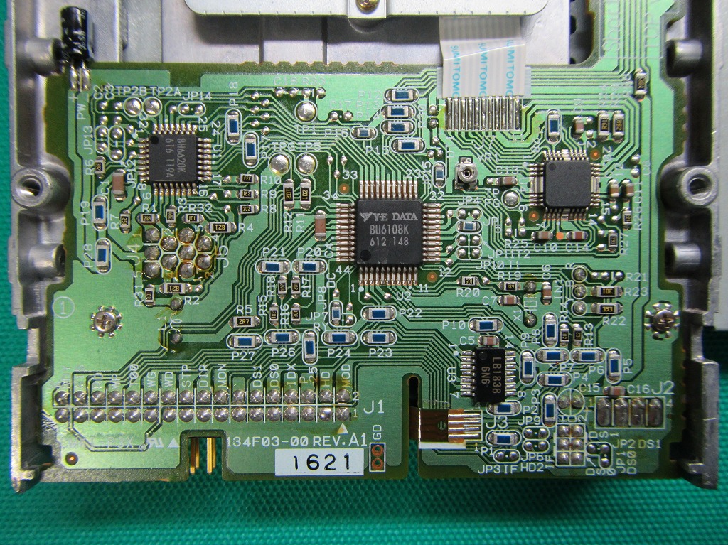
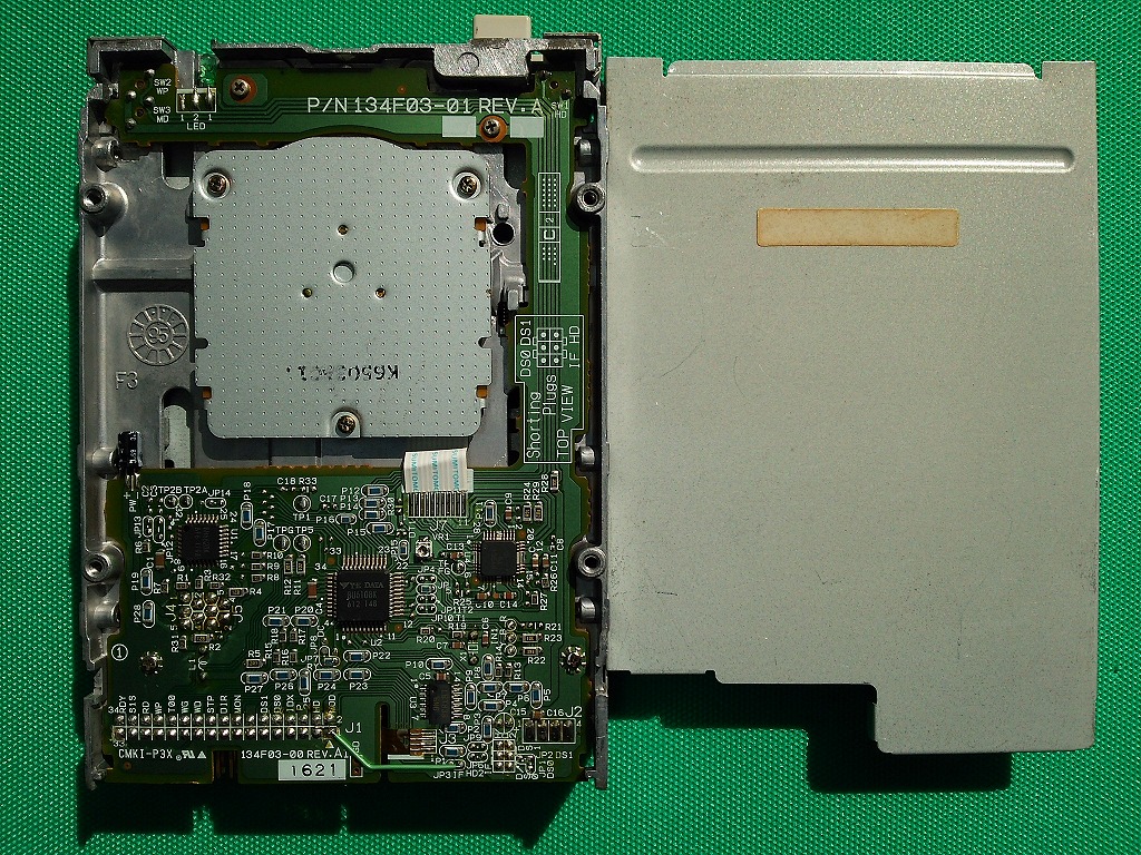
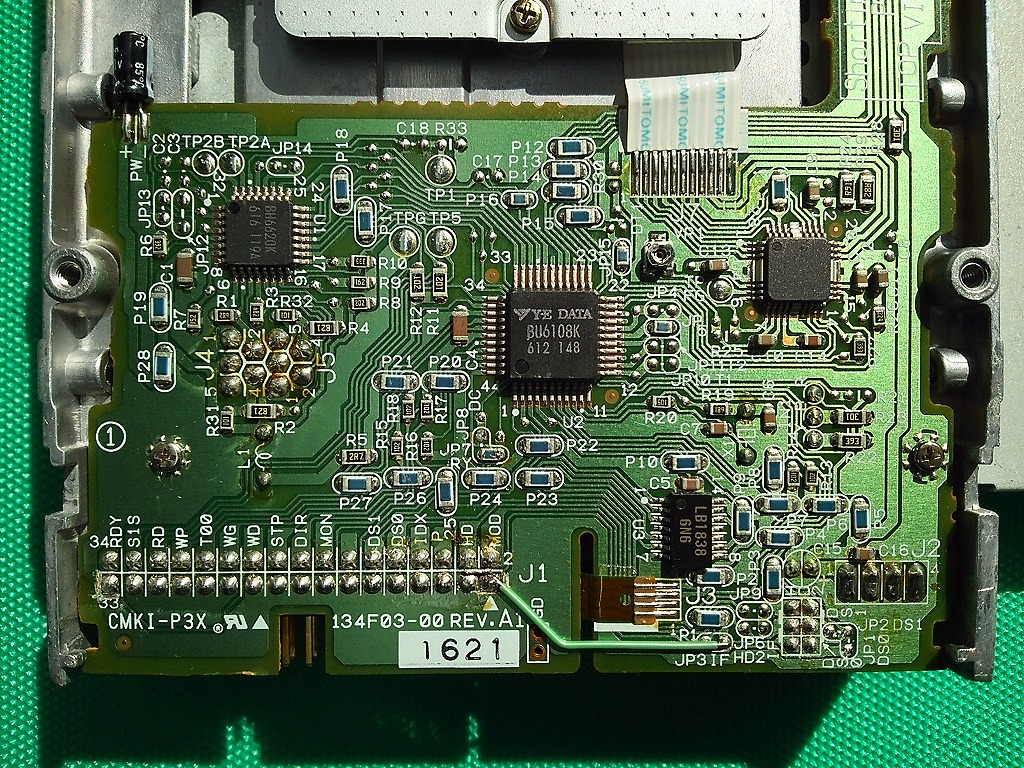
| YD-702D -6537D-A (BU6108K) [14pin] |
DXF | whole | Partial details |
whole | Partial details |
OK | OK | *7 | ||
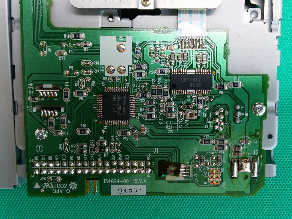
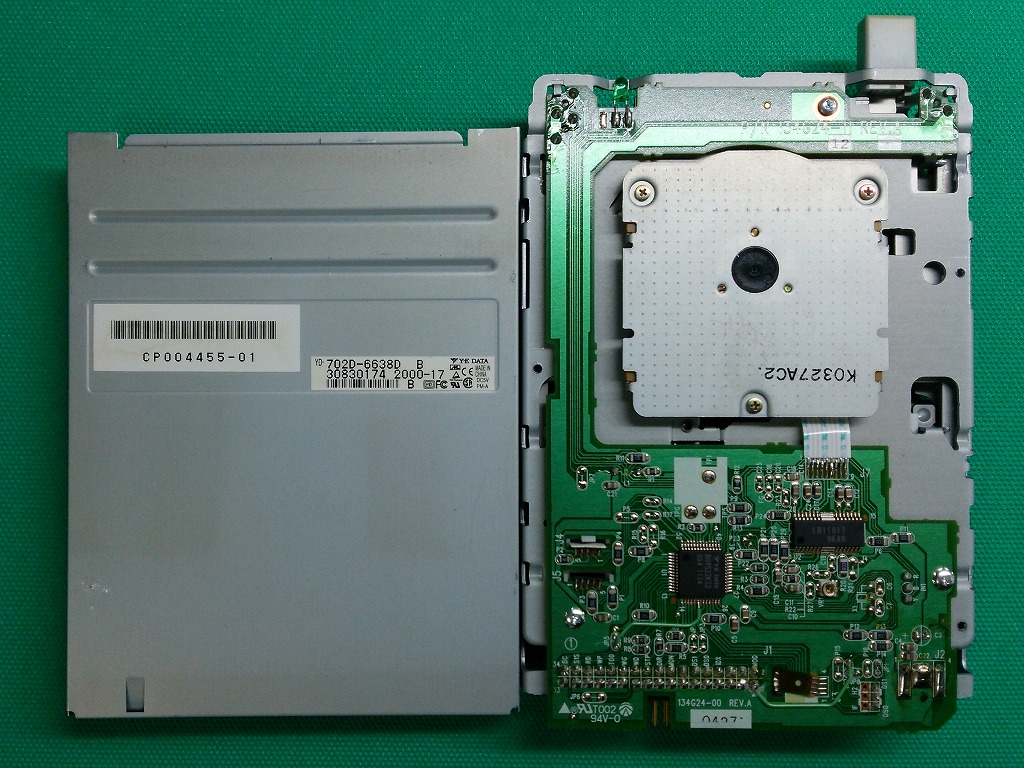
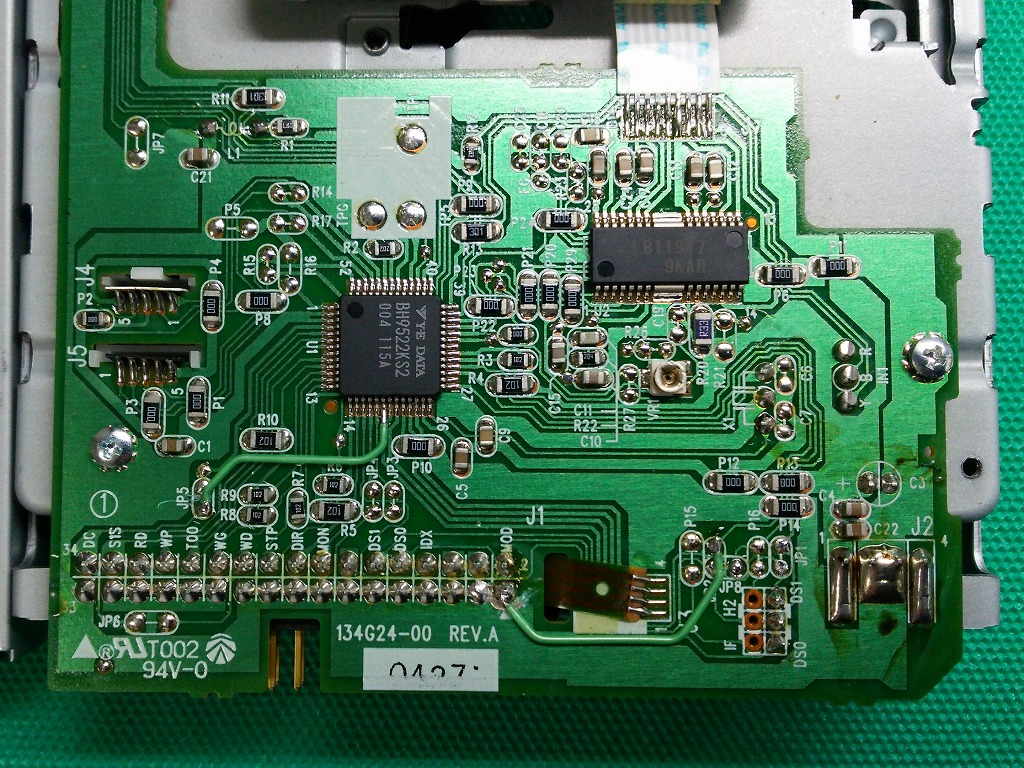
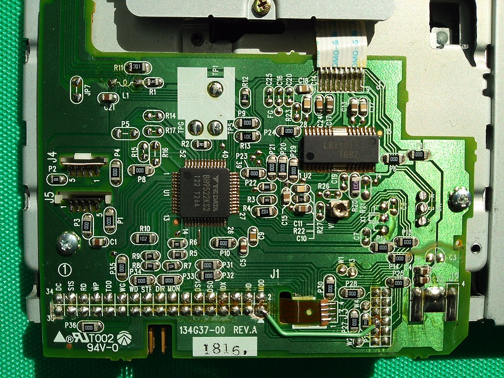
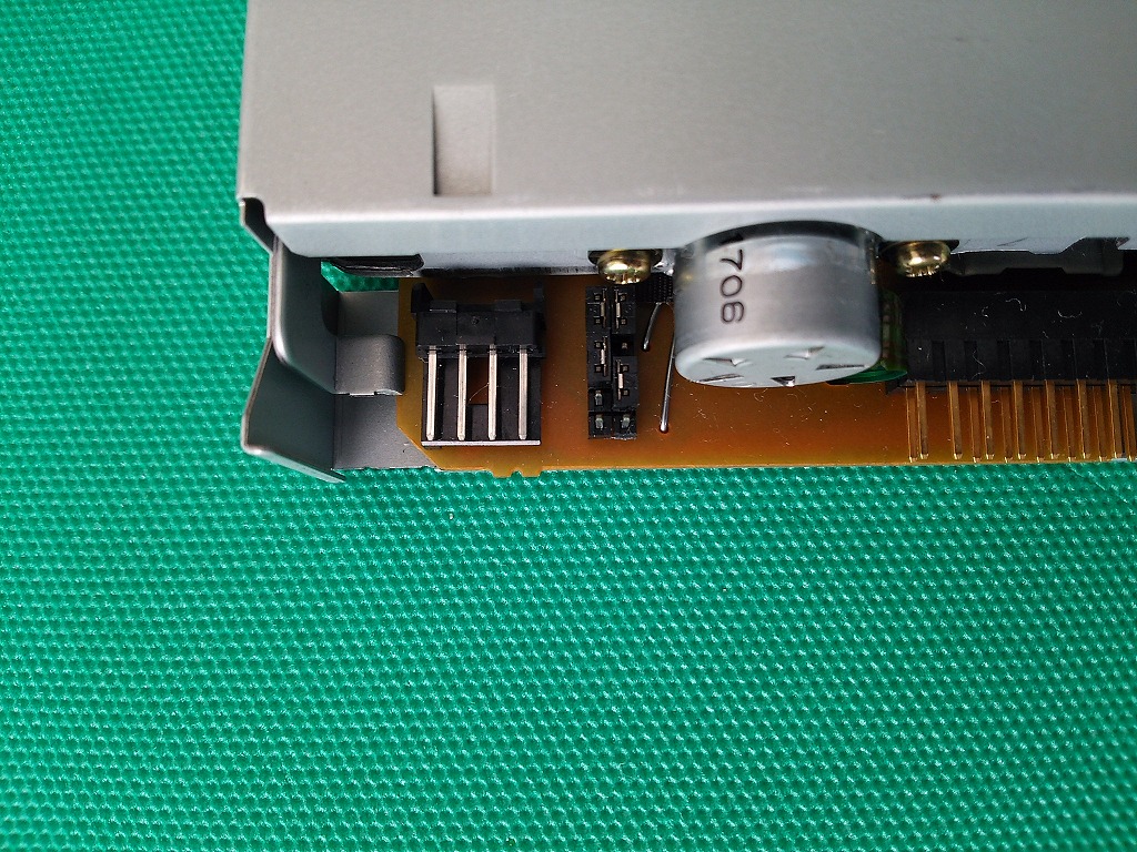
| YD-702D -6638D (BH9522KS2) [19pin] |
DXF | whole | Partial details |
whole | Partial details |
OK | OK | *7 | ||
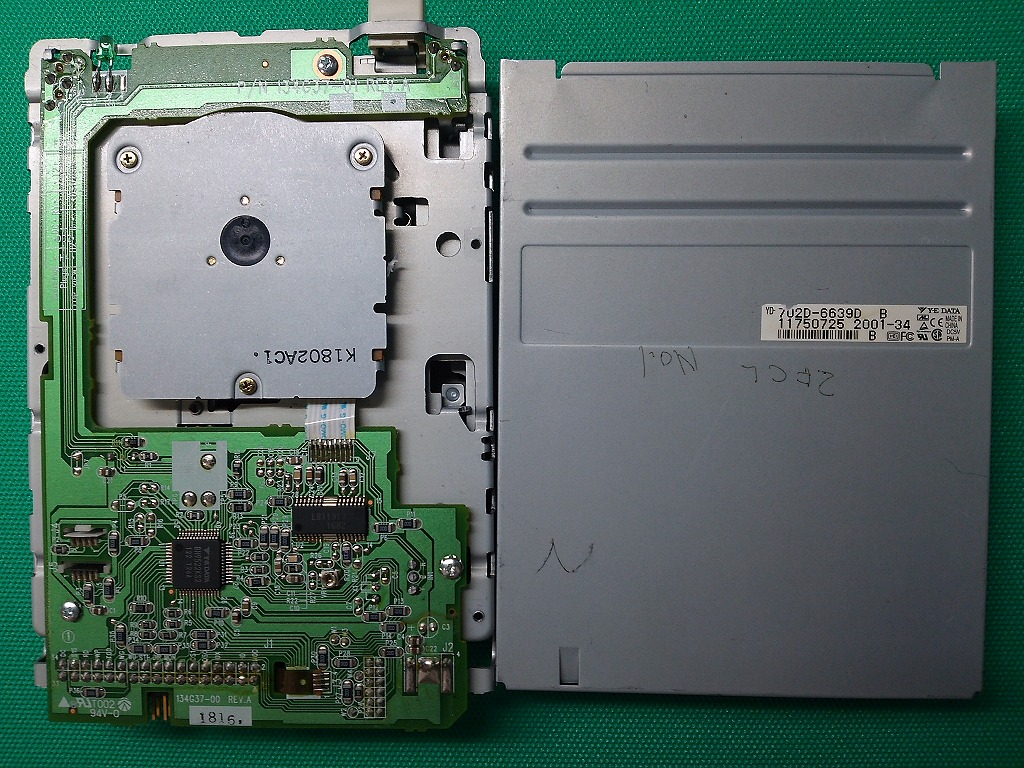
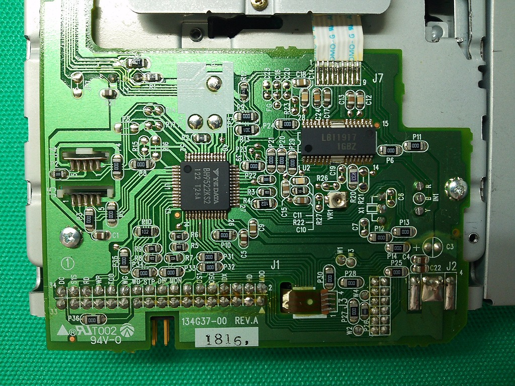
| YD-702D -6639D (BH9522KS2) [19pin] |
DXF | whole | Partial details |
whole | Partial details |
OK | OK | |||
For this FDD, it is necessary to modify the jumper. For details of jumpers, refer to the separate drawing ( Jumper Setting Table ( Y-E DATA YD-702D-6639D ) ) . |
||||||||||
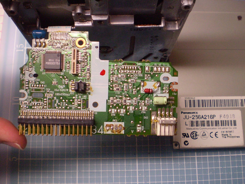
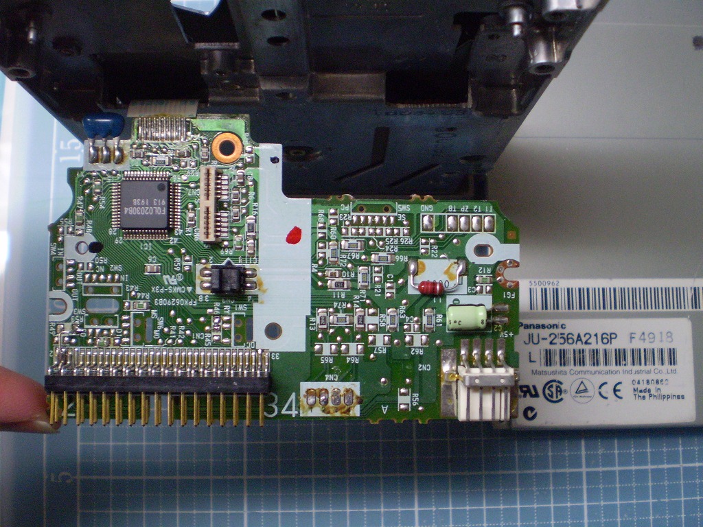
| JU-256A 216P (FQL02030B4) |
DXF | whole | Partial details |
whole | Partial details |
OK | OK | *7 | ||
|
In order to modify this FDD, it is necessary to remove and reattach the FPC and FFC cables for the stepping motor of the head in addition to the control board at the same time. Once the control board is removed, it is necessary to adjust the position of various sensors in micrometer steps. Therefore, although reference drawings of this FDD are provided, we recommend avoiding modifications as much as possible. In the case of switching only between Disk Change and Ready signals, there is a method of modification without removing the control board. Specifically, after moving the head to the innermost side, "R45" and "R46" related to switching are modified through the gap between the head and frame inside the FDD. With this method, misalignment of various sensors can be prevented. |
||||||||||
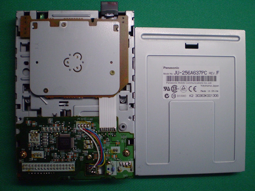
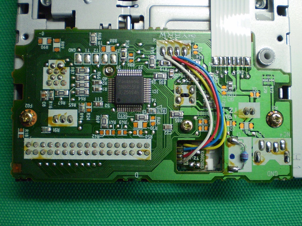
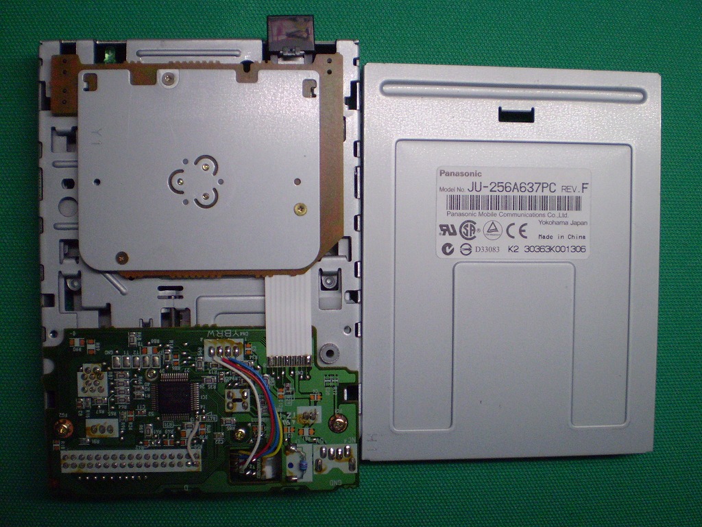
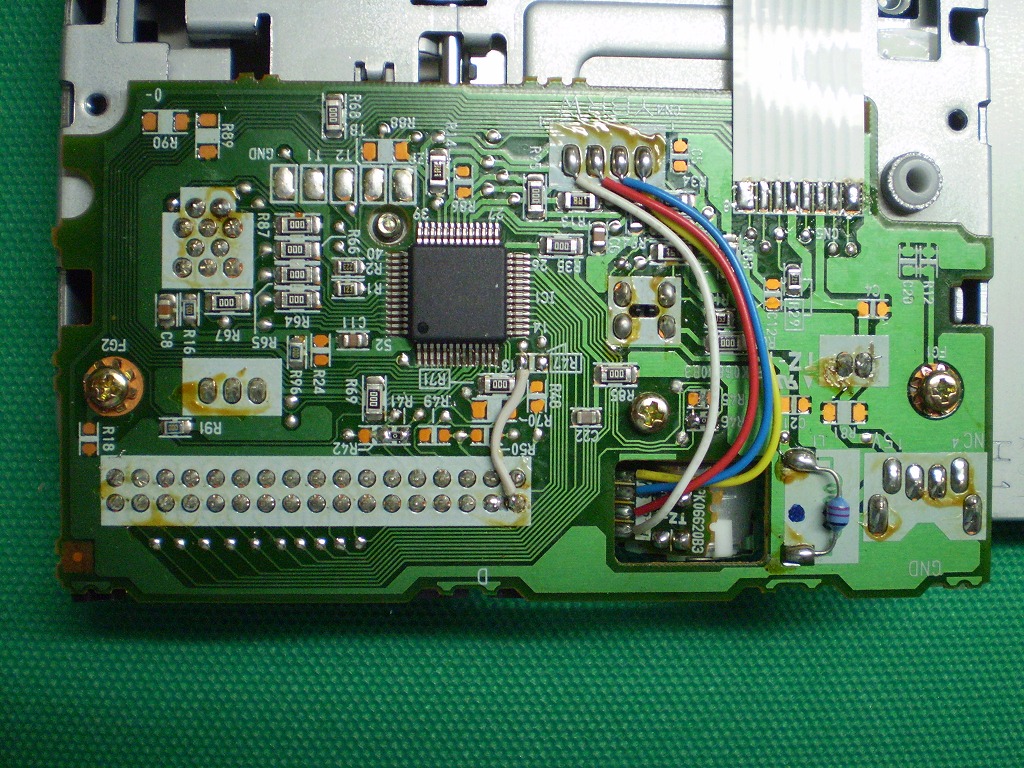
| JU-256A 637PC (DN8655FA) [28pin] |
DXF | whole | Partial details |
whole | Partial details |
OK | OK | *7 *11 |
||
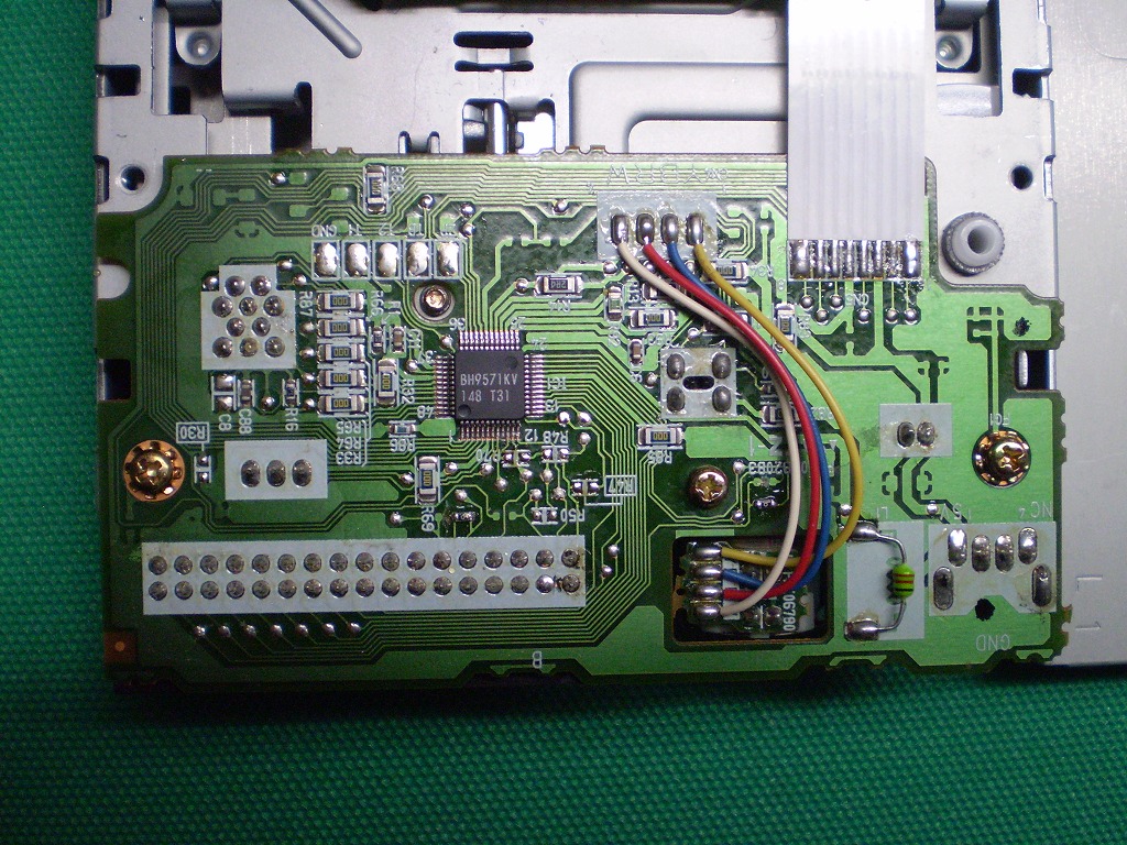
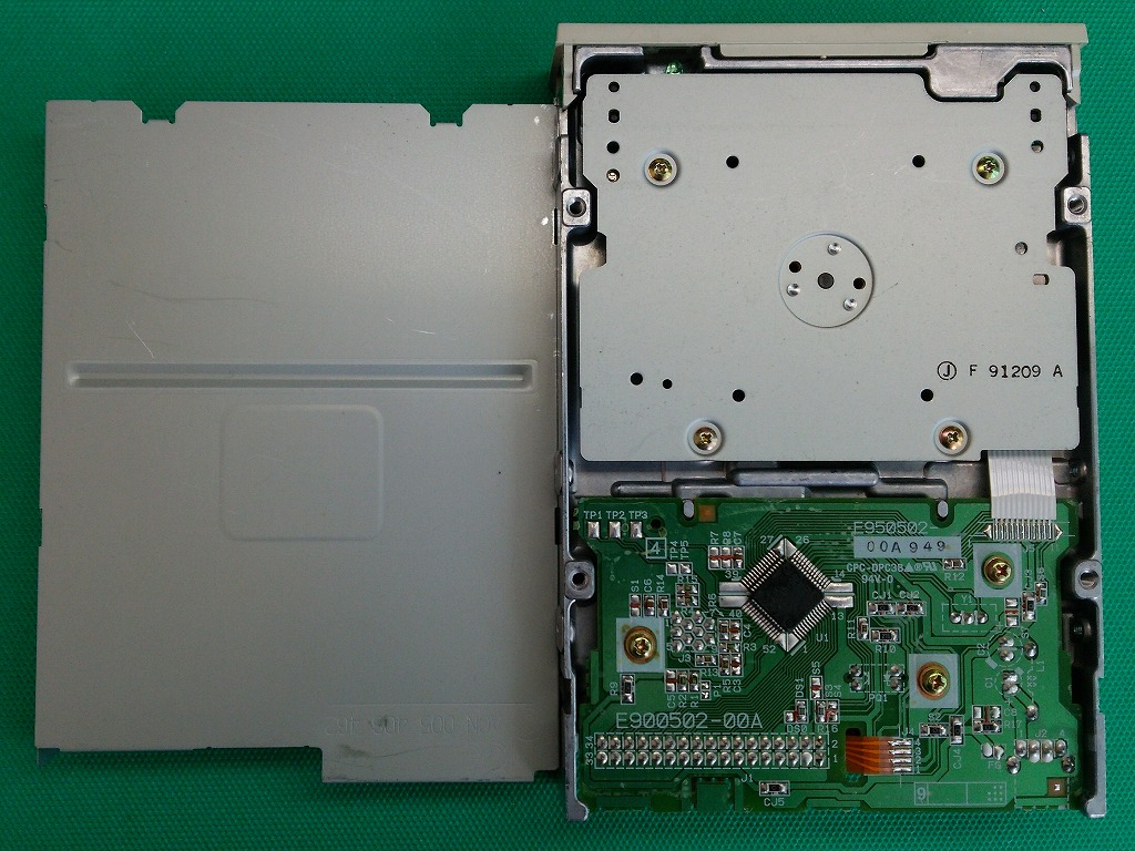
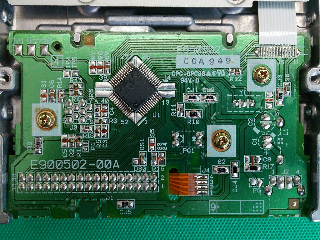
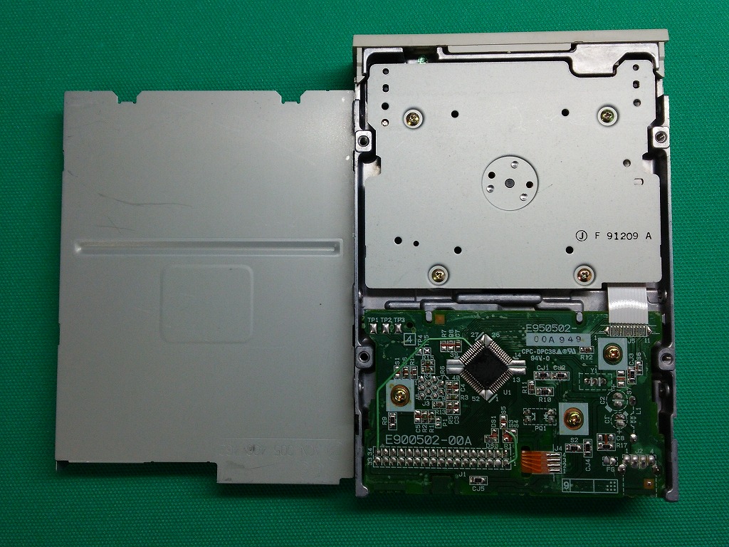
| JU-257A 137P (BH9571KV) [24pin] |
DXF | whole | Partial details |
whole | Partial details |
OK | *7 *17 |
|||
| FD-235HG -A304-U5 (TB6048) [31pin] |
DXF | whole | Partial details |
whole | Partial details |
OK | OK | *7 *12 |
||
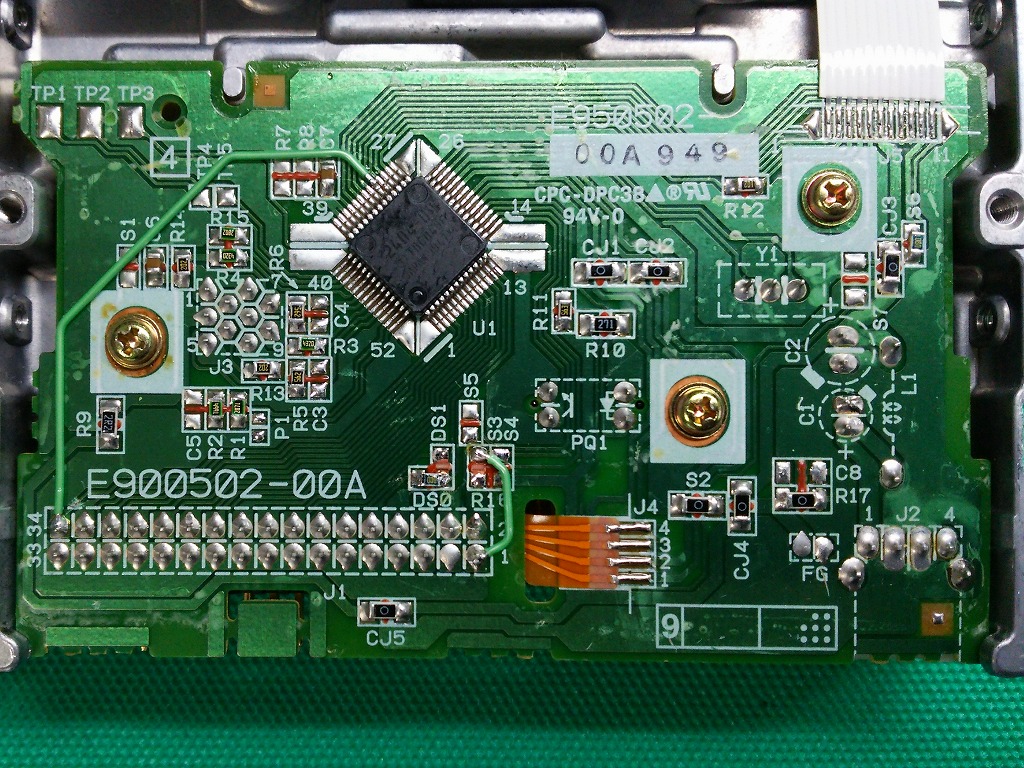
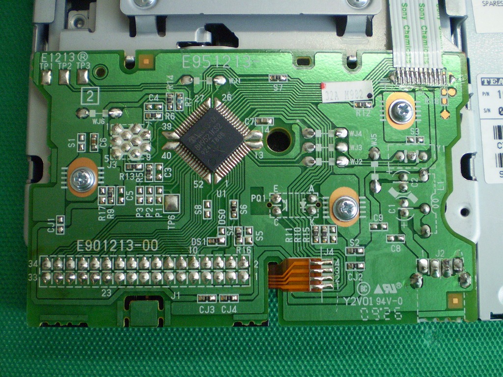
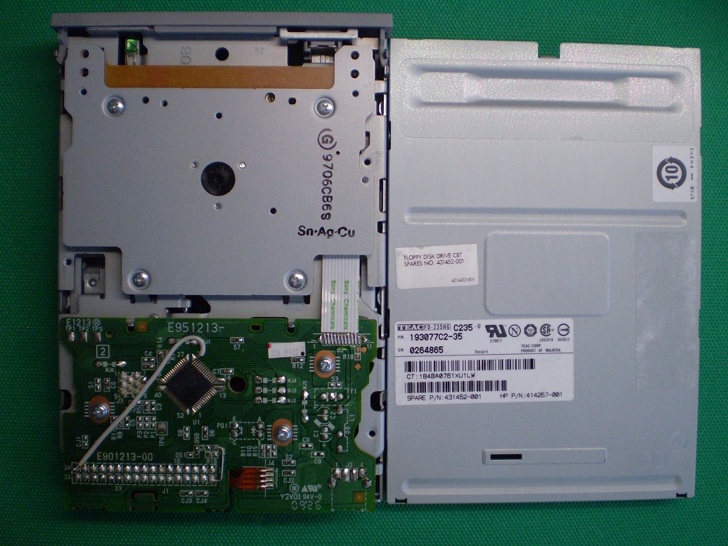
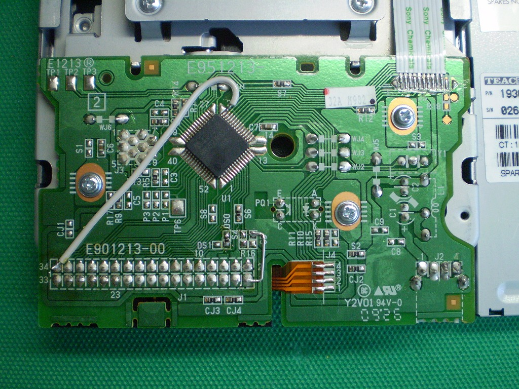
| FD-235HG -C235-U (BH9521KS2) [26pin] |
DXF | whole | Partial details |
whole | Partial details |
OK | OK | *7 *13 |
||
| FD-235HG -6360-U (BH9503GKS2) [10pin] |
DXF | whole | Partial details |
whole | Partial details |
OK | *7 | |||
For this FDD, it is necessary to modify the jumper. For details of jumpers, refer to the separate drawing ( Jumper Setting Table ( TEAC 3-row type ) ) . |
||||||||||
| FD-235HG -7304-U5 (TB6022AF) [10pin] |
DXF | whole | Partial details |
whole | Partial details |
OK | *7 | |||
| FD-235HF -7304-U5 (BH9506GKS2) [10pin] |
DXF | whole | Partial details |
whole | Partial details |
OK | OK | *7 *19 |
||
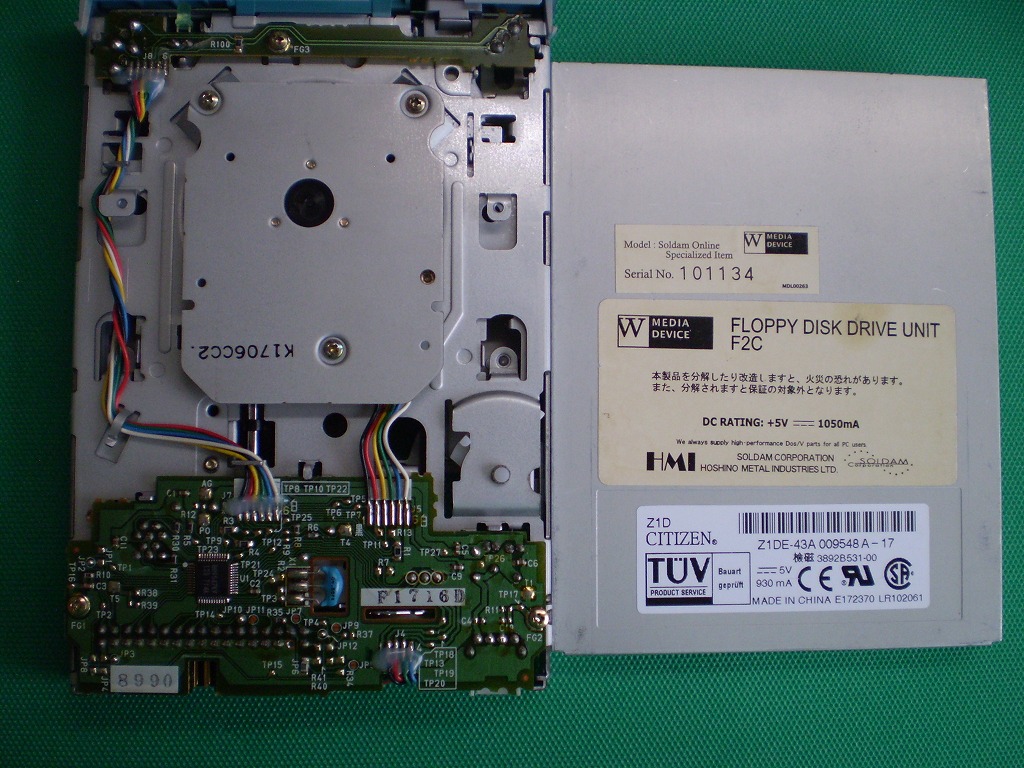
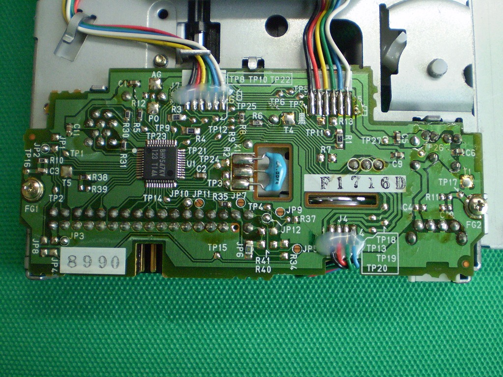
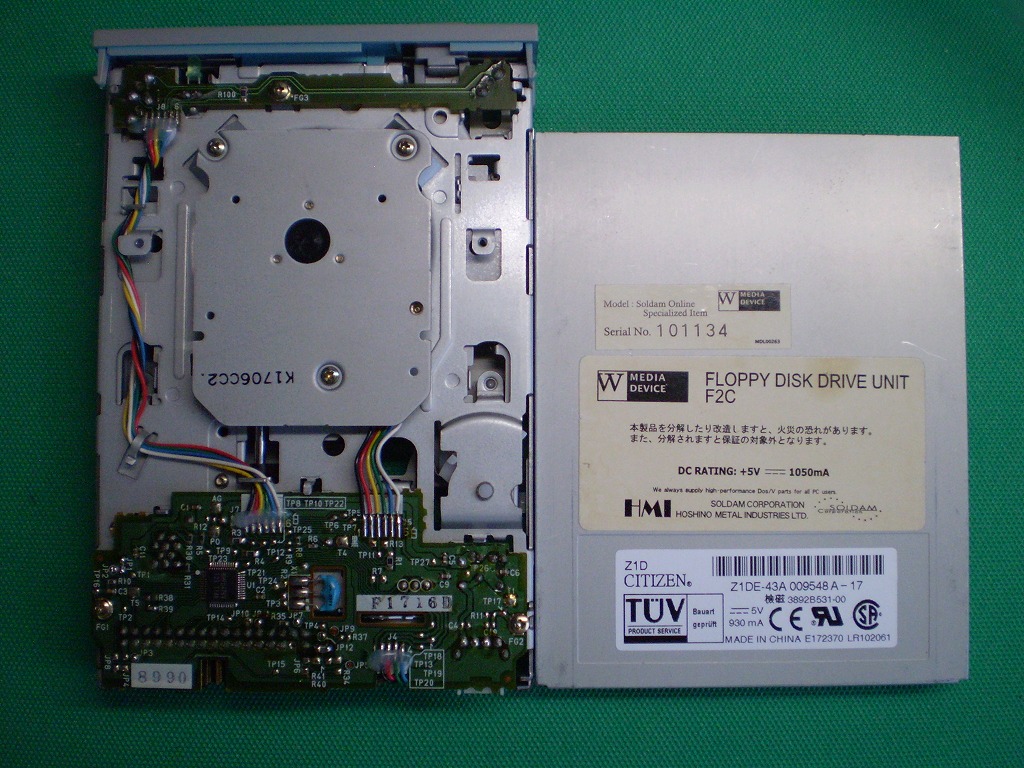
| Z1D (BH9547KV) [4pin] |
DXF | whole | Partial details |
whole | Partial details |
OK | OK | *7 | ||
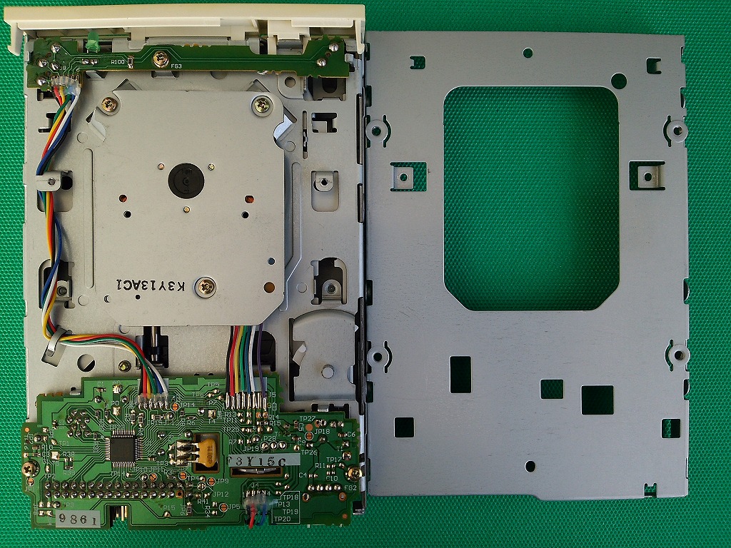
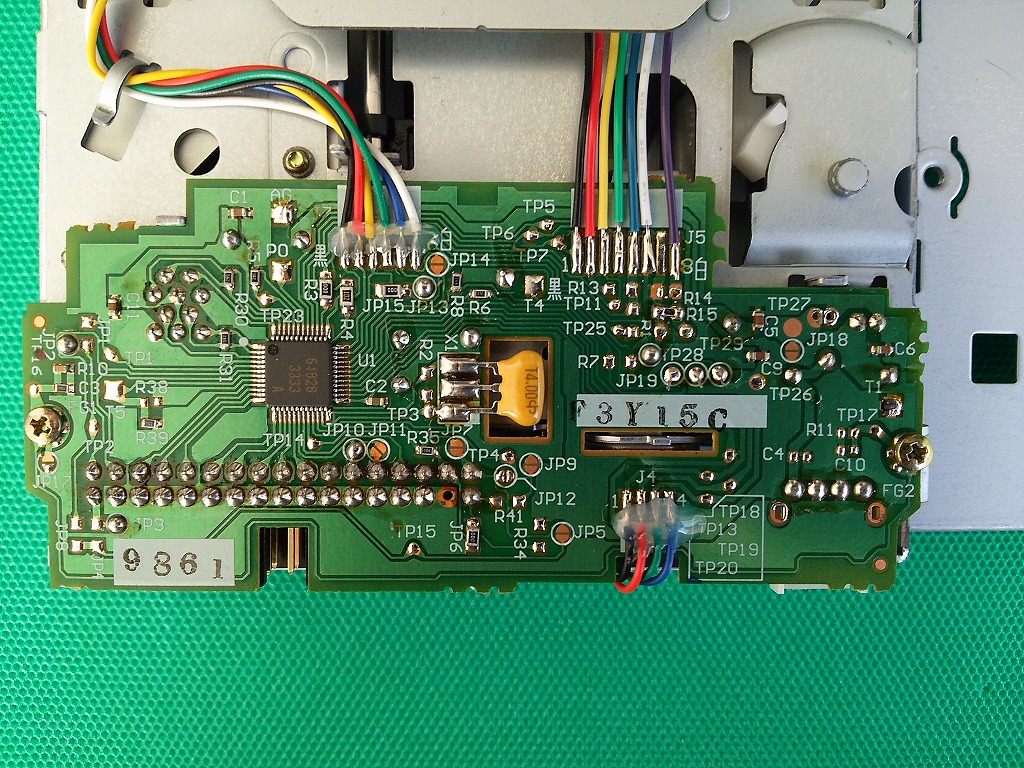
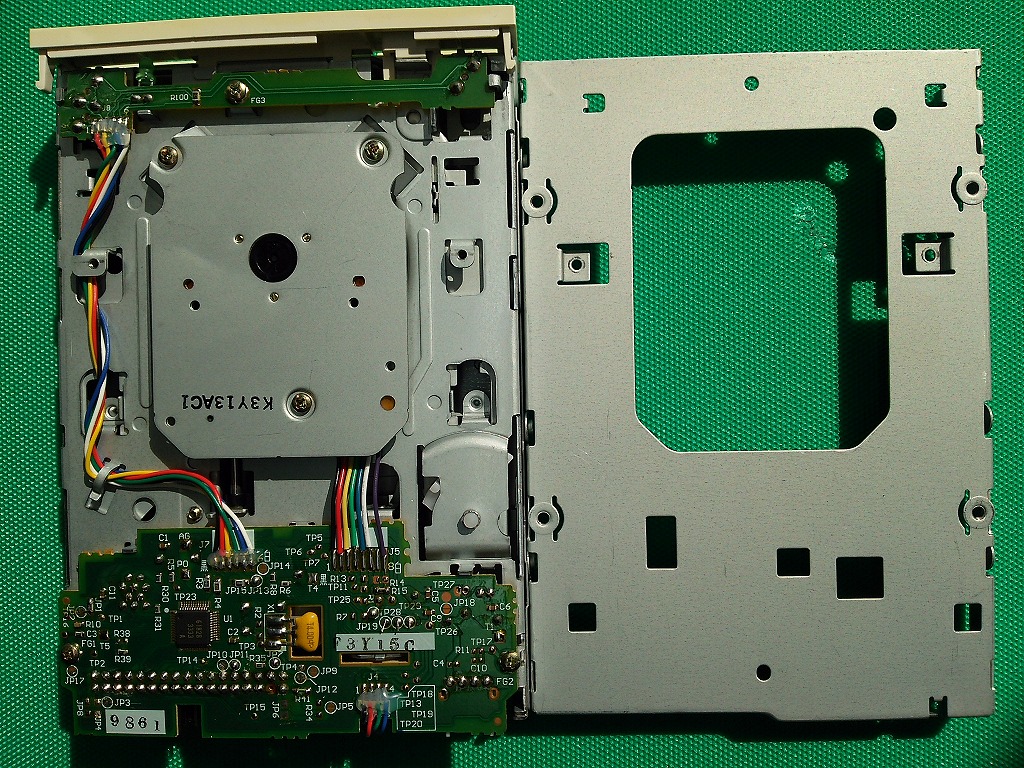
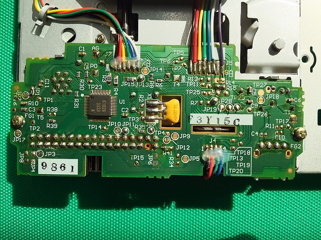
| Z1DA-89A (61828) [4pin] |
DXF | whole | Partial details |
whole | Partial details |
OK | OK | *7 | ||
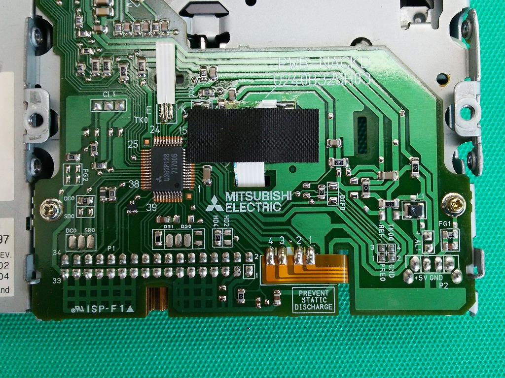
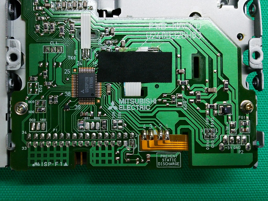
| MF-355F -3490UC (U262P128) [48pin] |
DXF | whole | Partial details |
whole | Partial details |
OK | OK | *7 | ||
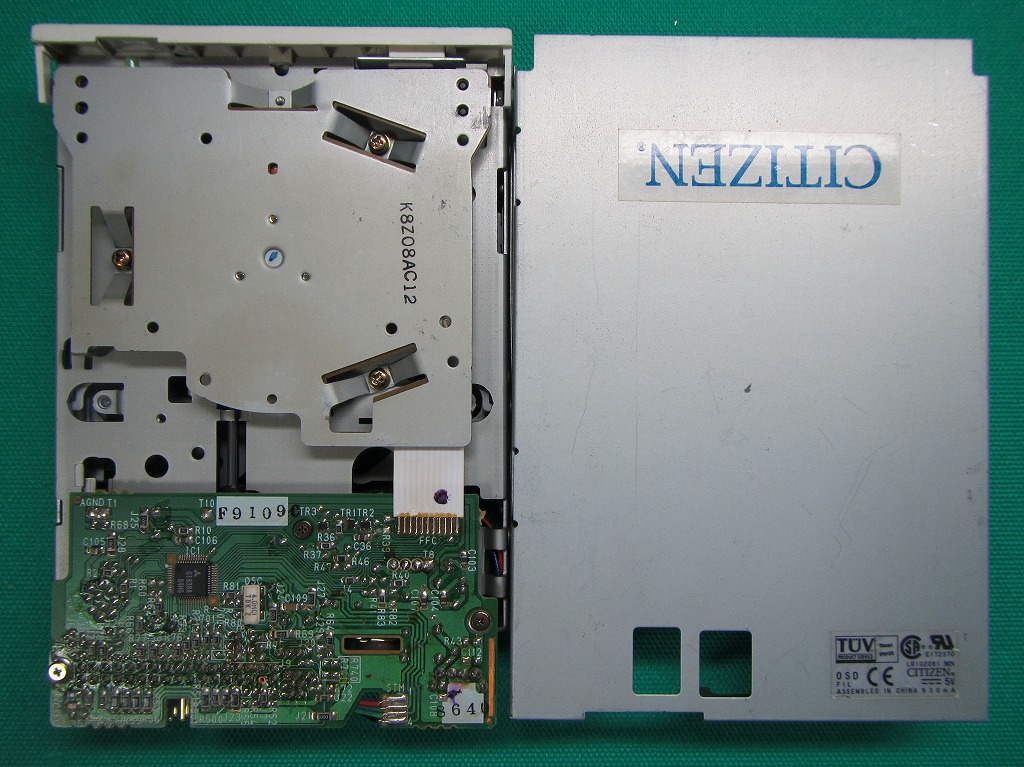
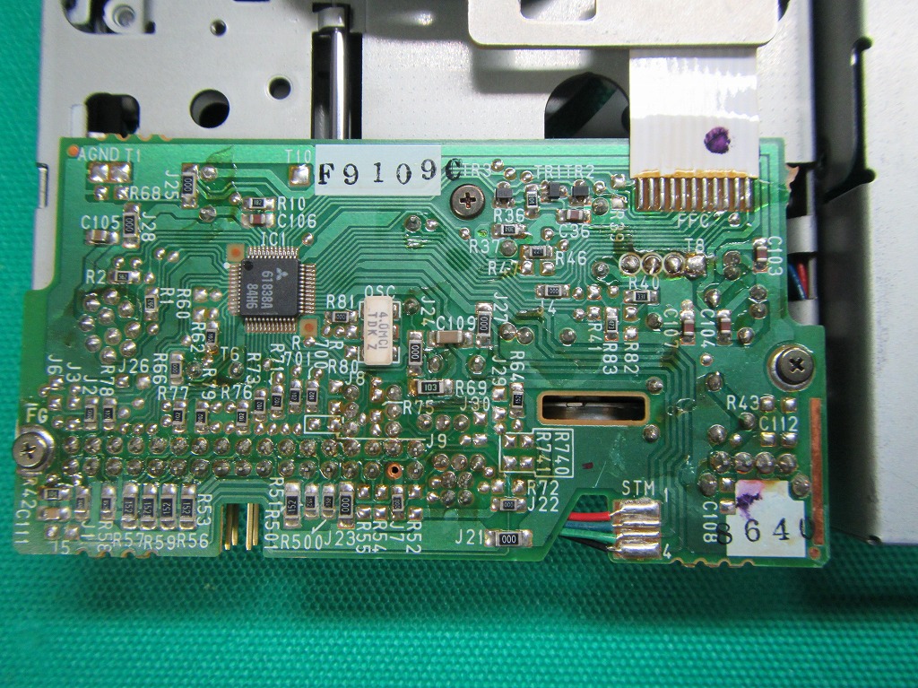
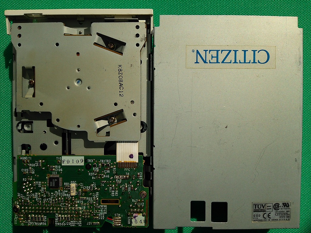
| OSD-FIL (61838A) [4pin] |
DXF | whole | Partial details |
whole | Partial details |
OK | *7 | |||
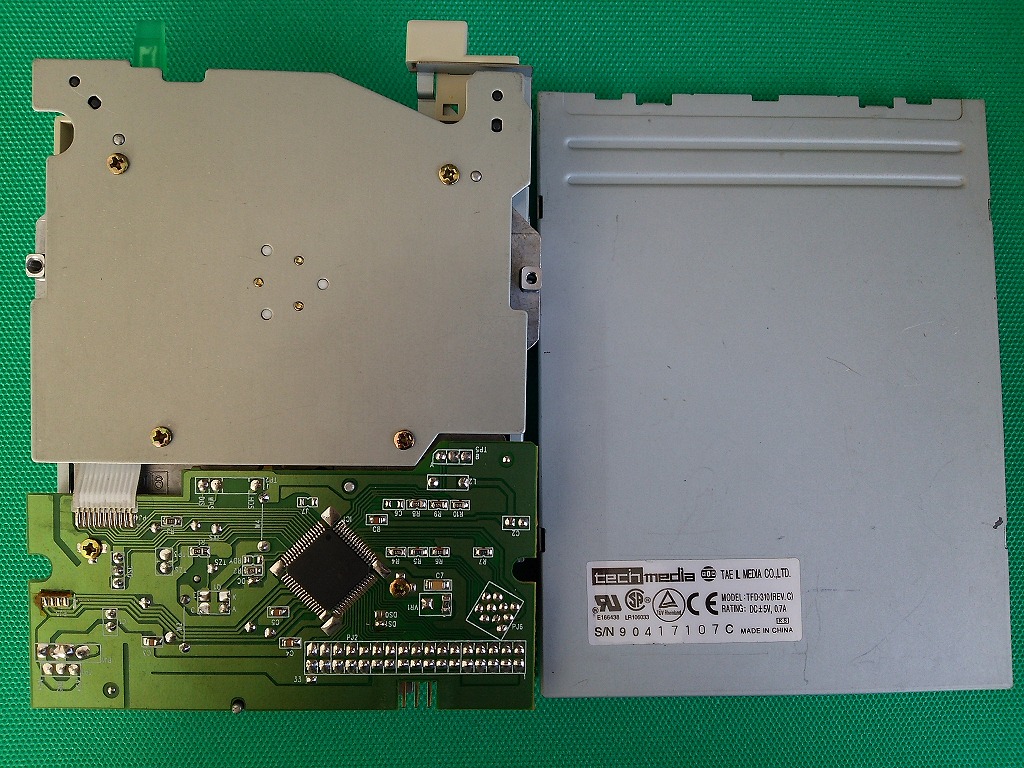
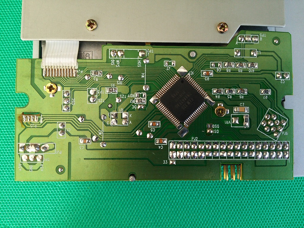
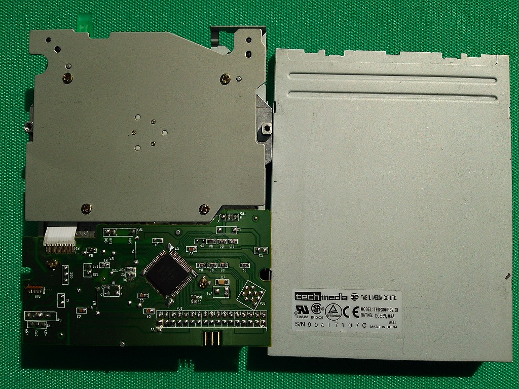
| TFD-310 (DN8862FAQ) [19pin] |
DXF | whole | Partial details |
whole | Partial details |
OK | *7 | |||
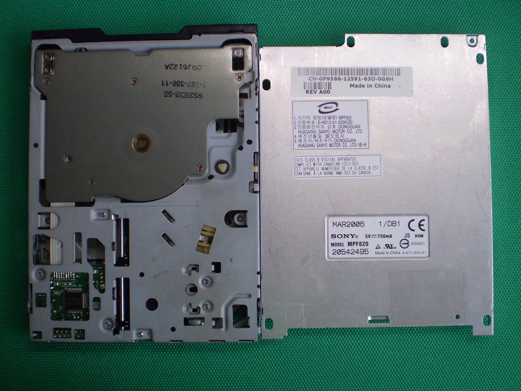
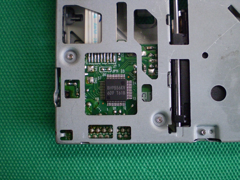
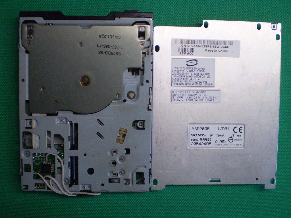
| MPF820 (BH9556KV) [15pin] |
DXF | whole | Partial details |
whole | Partial details |
OK | OK | *7 | ||
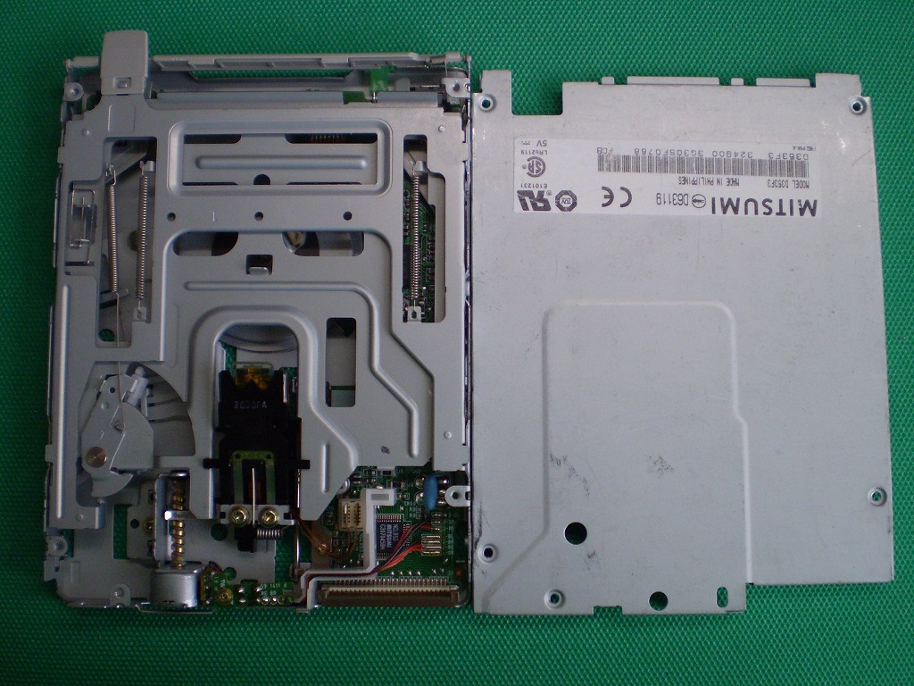
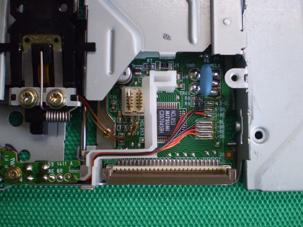
| D353F3 (NCL053) |
DXF | whole | Partial details |
whole | Partial details |
OK | OK | *7 | ||
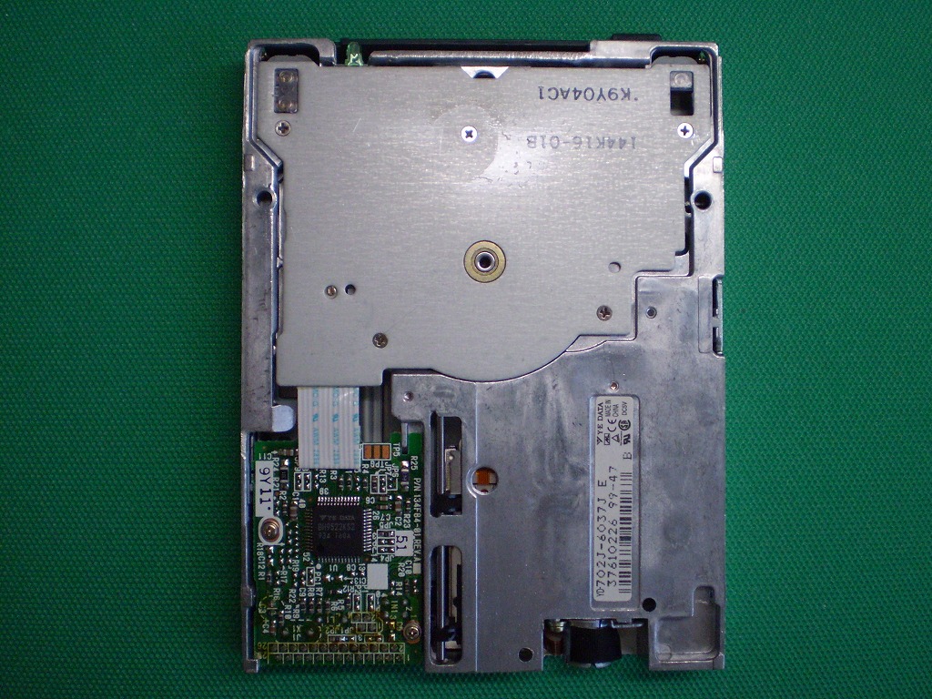
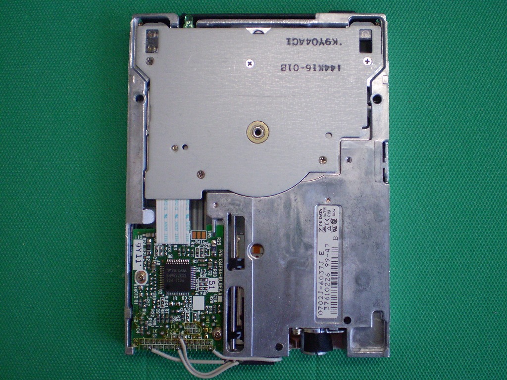
| YD-702J -6037J (BH9522KS2) [19pin] |
DXF | whole | Partial details |
whole | Partial details |
OK | OK | *7 *18 |
||
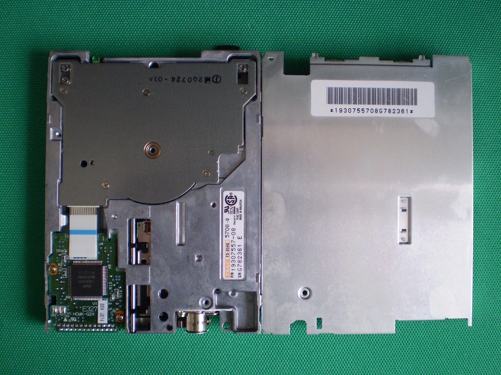
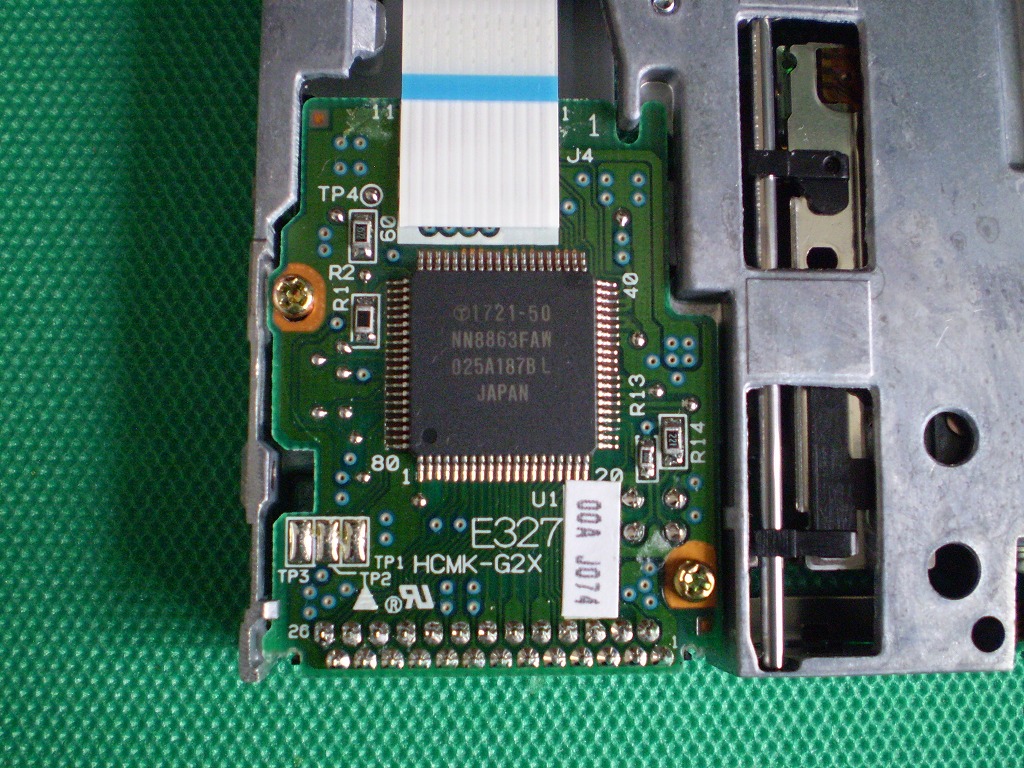
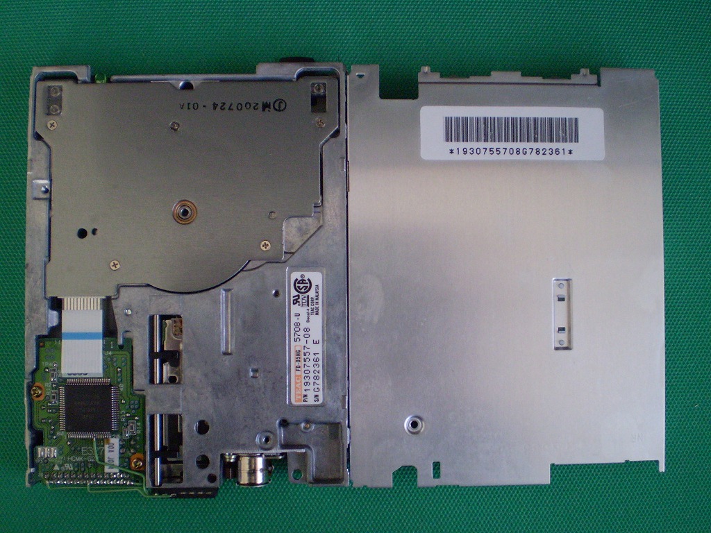
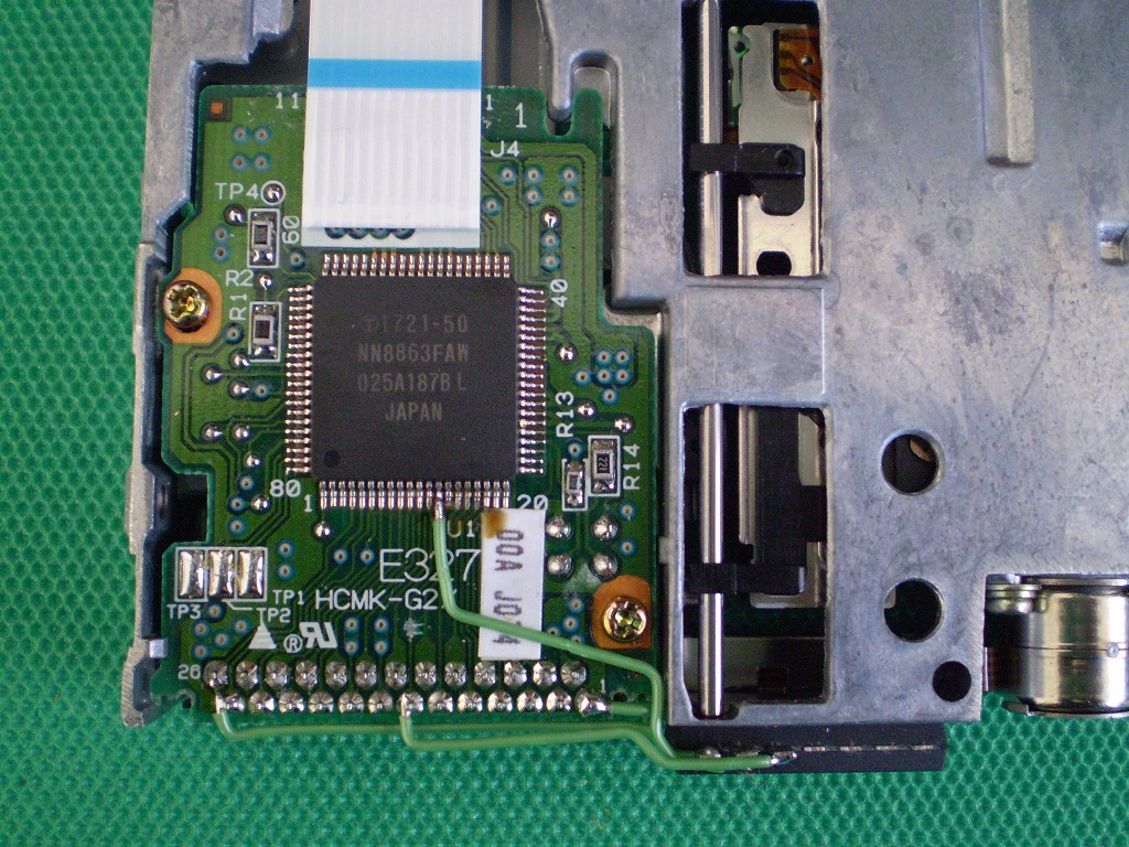
| FD-05HG -5708-U (NN8863FAW) [18pin] |
DXF | whole | Partial details |
whole | Partial details |
OK | ? | *7 *14 |
||
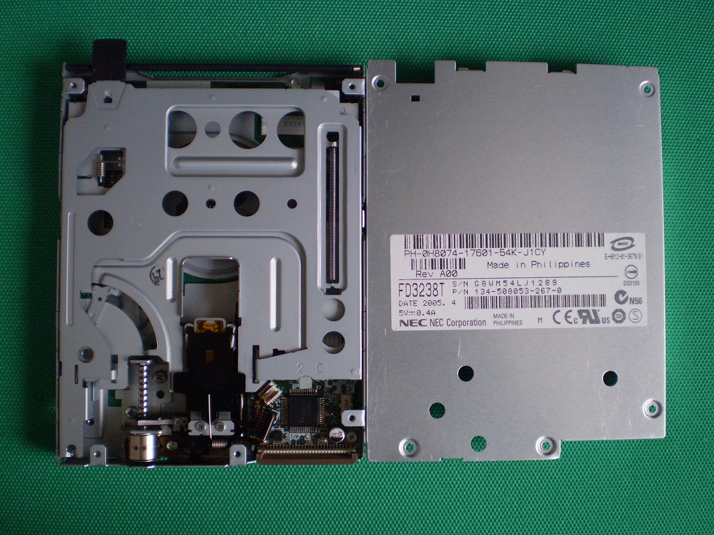
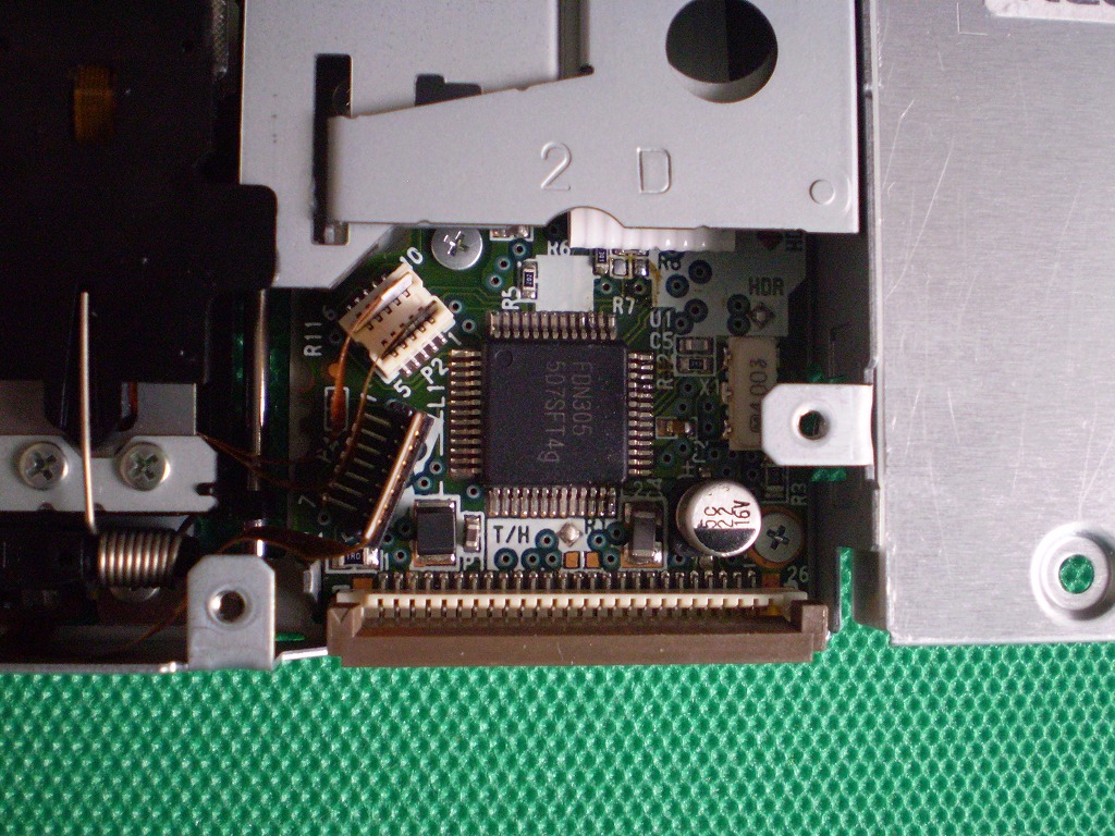
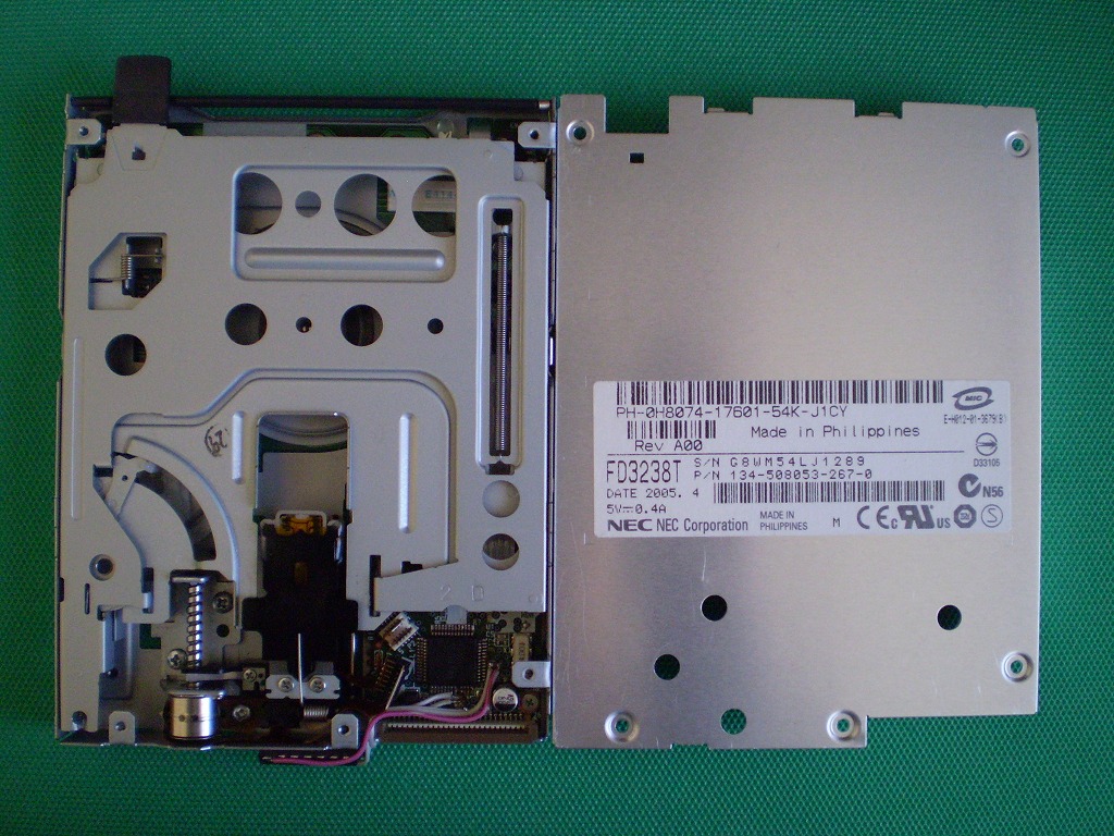
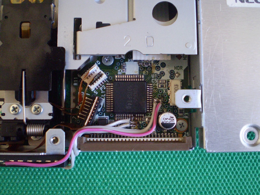
| FD3238T (FDN305) [6pin] |
DXF | whole | Partial details |
whole | Partial details |
OK | ? | *7 | ||
| MF355H -325MS (U262P149) |
DXF | whole | Partial details |
whole | Partial details |
OK | OK | *7 *20 |
||
|
||||||||||
The FD3238T listed in the above list is equipped with the same FDN30x series as the FD1231T as a control IC. I expected that 2DD could be used if the same modification as FD1231M was performed, but in reality 2DD could not be used.
If you modify the FD3238T in the same way as the FD1231M and then connect the FD3238T to the PC-9821 Ls12 to access the FD, the disk will be recognized but will be displayed as "unformatted" and will stop. After that, any attempt to format it will fail.
Upon closer examination, it was found that even if it was modified, the limit was to invert the 360/300 signal and input it, and it was concluded that 2DD could not be used.
The cause is unknown, but it is believed to be an abnormality in the control of the head section. If the cause can be identified, it will be possible to use 2DD on the PC-9821 series.
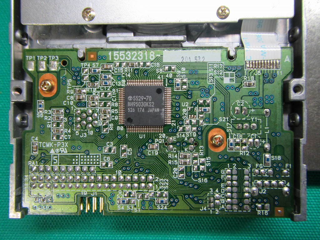
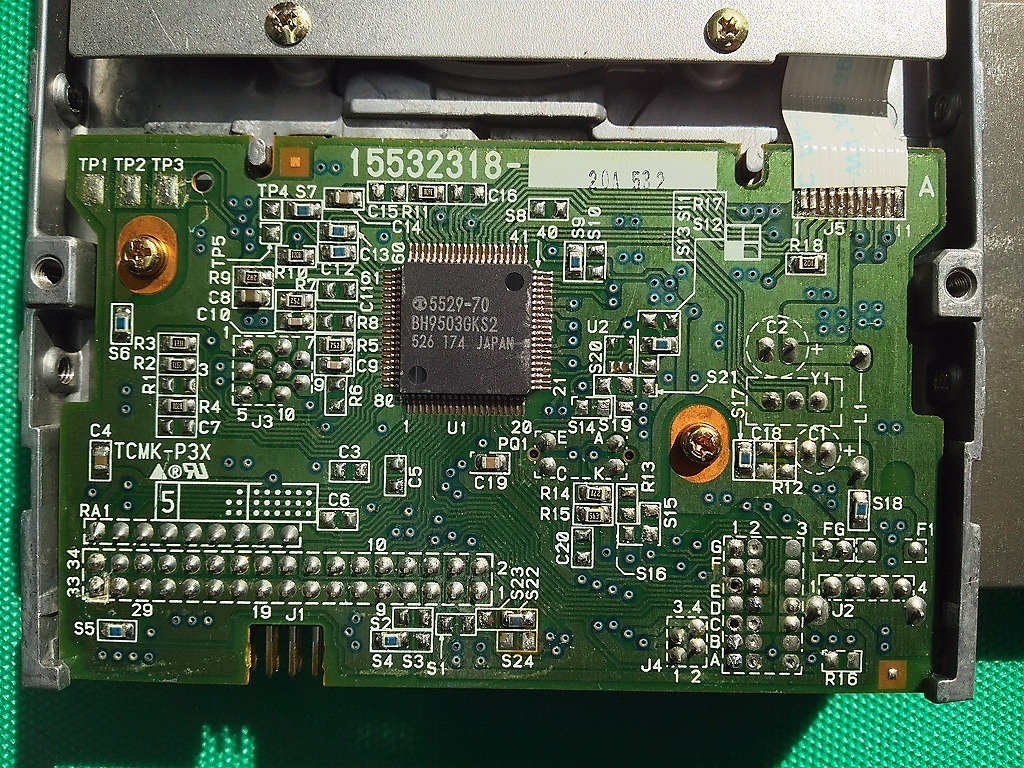
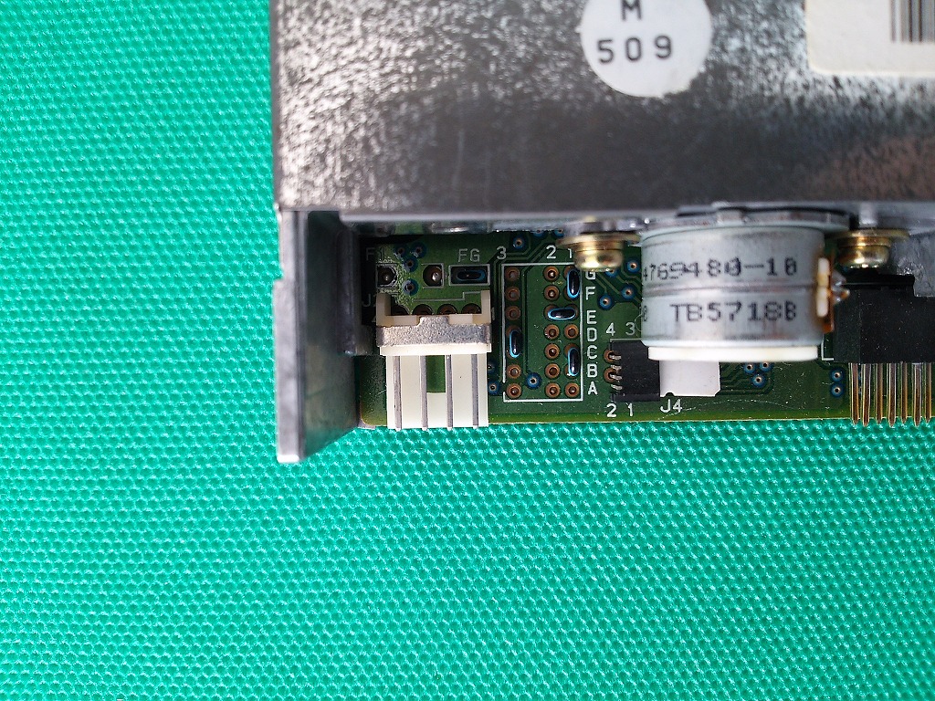
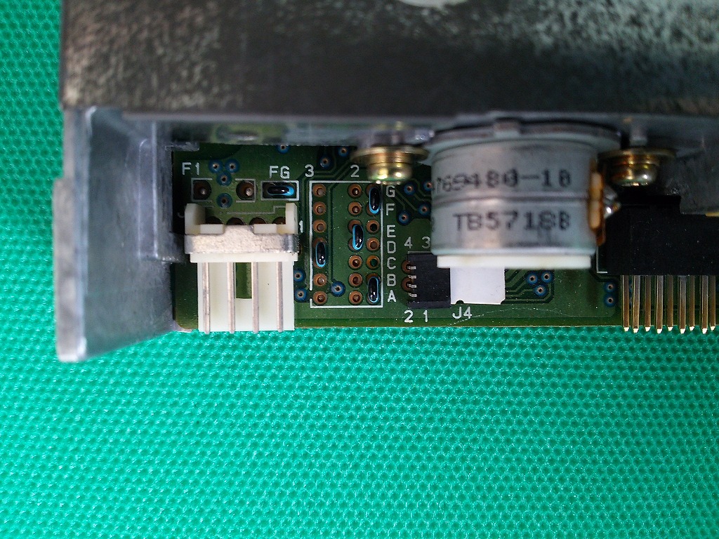
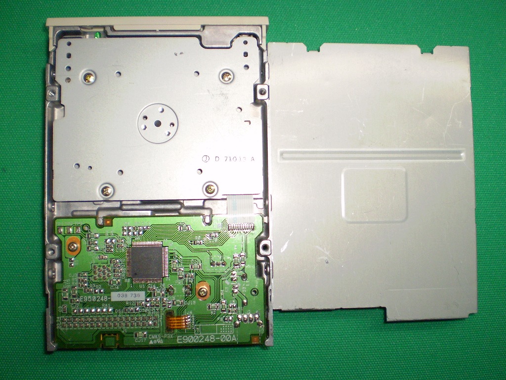
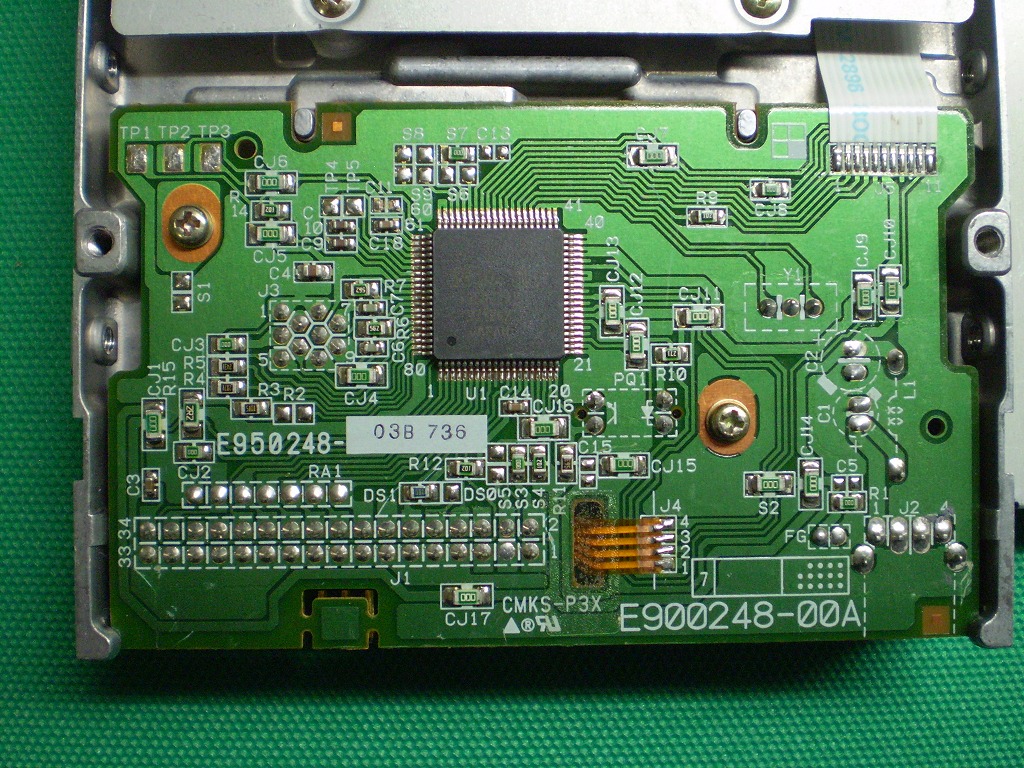
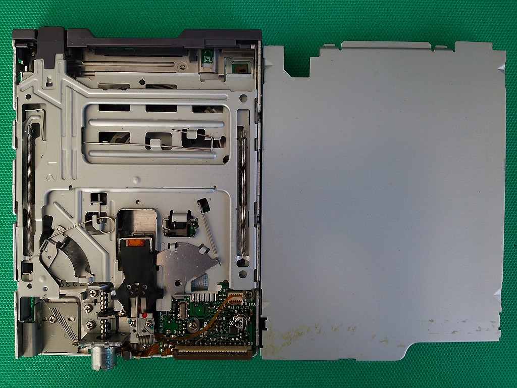
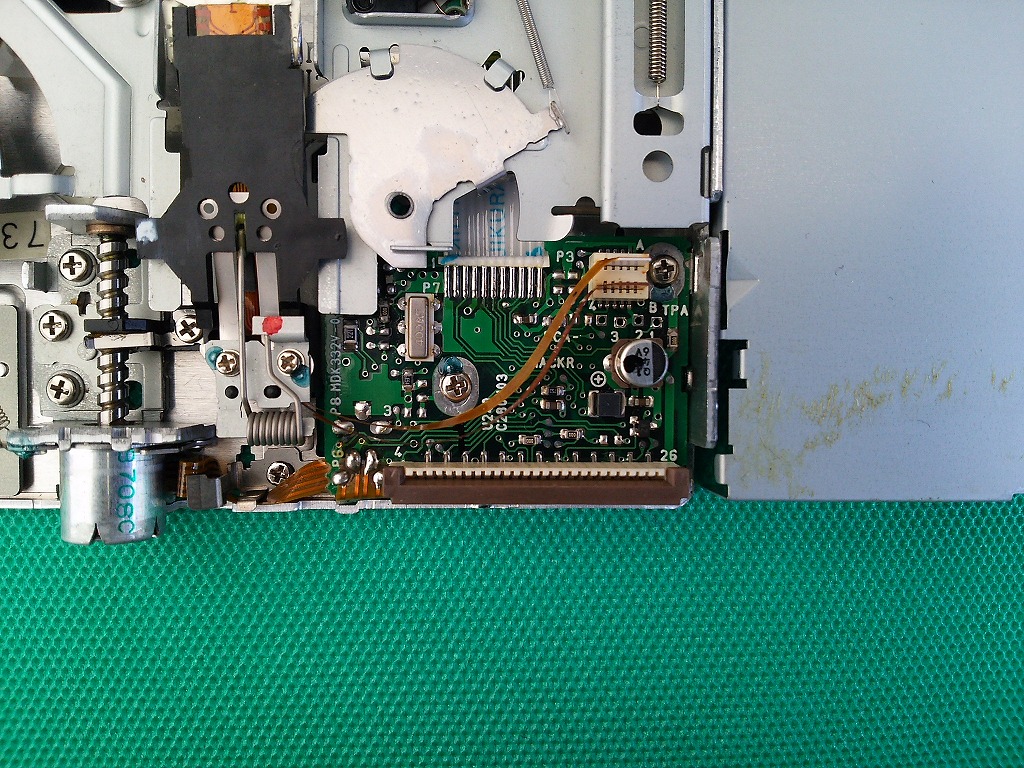
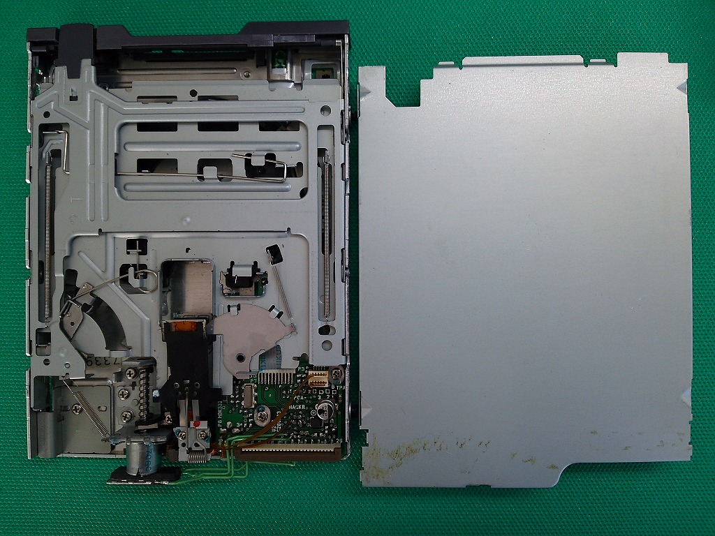
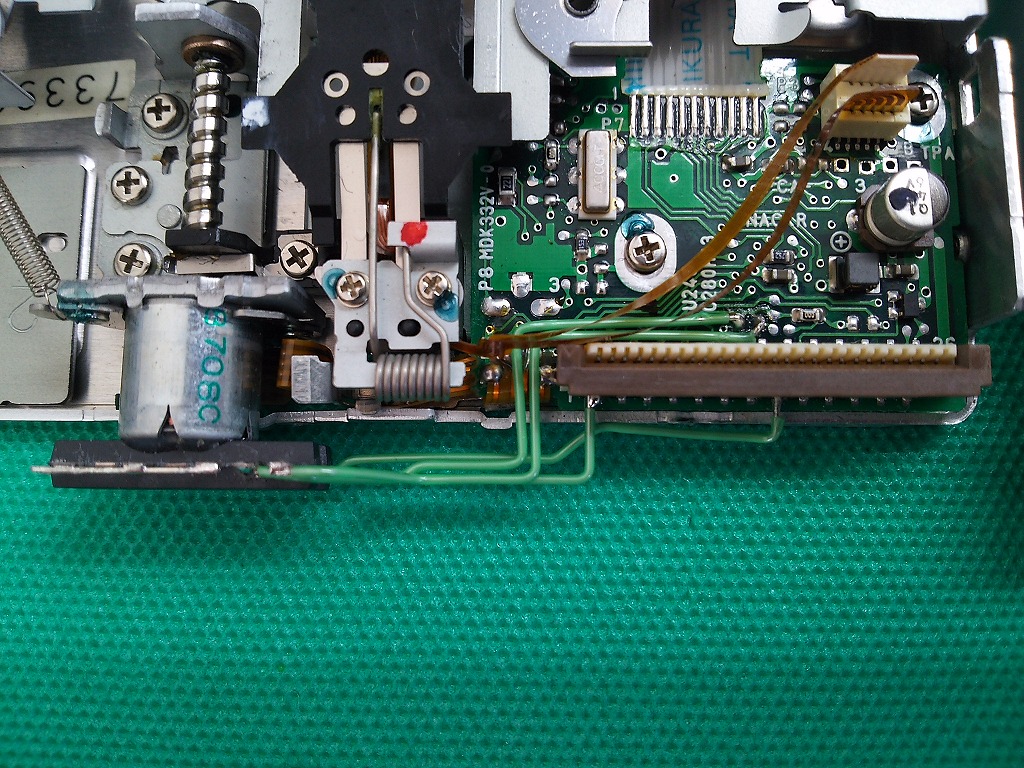
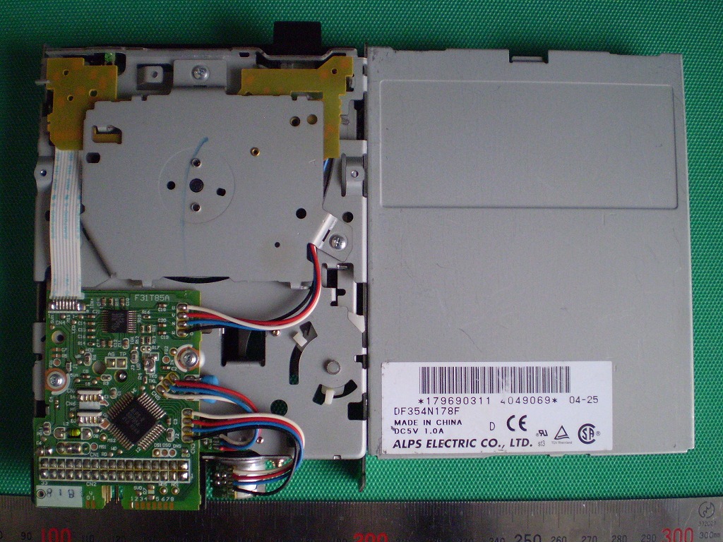
Although the DF354N178F can output the Ready signal, for some reason it did not work well with the PC-9821 Ls12. The Ready signal output point is shown for reference.
DF354N178F Reference
Whole board
Ready signal output point
References
Copyright (C) 2022 "shiunten"